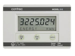
Contrec 212.21N0.S

This is the wall mounting version of the Contrec 212 BTU Heat Calculator, fitted with a 4-20mA analogue output, running on DC power, and without a temperature probe pair included. We see this configuration ordered when the energy reading itself needs to go somewhere else, for example back to a BMS or SCADA system for trending or alarm purposes, on top of what is shown on the local display.

Wall mounting with standard cable gland entries means the unit sits on a wall or support bracket near the pipework rather than flush into a panel door, which most customers prefer when the calculator needs to sit close to the flowmeter and sensor wiring. The 4-20mA output is a straightforward proportional signal representing the energy or power reading, and it is worth confirming with us early whether you need it scaled to a specific range, since that is set at commissioning. No probe is included here because this variant is meant for customers who already have their own matched Pt100 or Pt1000 sensor pair installed in the flow and return lines.

The OIML R75 compliance matters if this reading feeds into cost allocation or billing between tenants or departments, since it meets the metrology standard usually expected for that. Before we quote this configuration, we would normally confirm the sensor pair type and cable length the customer already has, the exact 4-20mA scaling required, and the DC supply voltage available on site. Hope this helps.
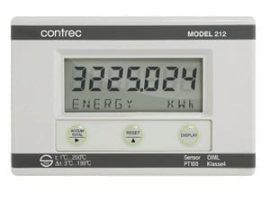
Contrec Model 212 Heat Calculator Technical Specifications
● GENERAL
DescriptionThe 212 Heat Calculator is designed to measure the energy consumed in hot water heating systems and chilled water cooling systems. It is a high-accuracy heat calculator designed to operate with digital output flowmeters, housed in an IP67 weatherproof case with a tactile keyboard and various mounting options. The unit can be supplied complete with temperature probes and interfaces with a wide range of flowmeters, including positive displacement and inferential water meters, magnetic flowmeters with pulse outputs, and turbine and paddle wheel flowmeters.
Key FeaturesHigh accuracy; 4-20mA output option; 4-wire PT100 RTD temperature inputs; heating, cooling and air conditioning; calculates and displays volume, energy, temperature and peak energy; built-in density and enthalpy tables; Meter-bus interface and RS485 communications; fully programmable; multilingual capability; metric or US units; watertight to IP66 (NEMA 4X); complies with OIML R75 and EN1434 standards; CE compliant.


● MODES OF OPERATION
Heating ModePositive ∆t’s only are totalised.
Cooling ModeNegative ∆t’s only are totalised.
Heating/Cooling ModeThe flow of energy may be for heating or cooling; the energy total is increased regardless of whether ∆t is positive or negative.
Charge/Discharge ModeTwo separate registers totalise positive and negative totals.


● FUNCTIONAL DESCRIPTION
Density & Enthalpy CalculationThe 212 measures temperature in the feed and return lines and, from this, calculates the density and enthalpy of the water. By also measuring the volume of water flowing in the system, the 212 computes the energy consumed. Power is calculated as: P = V x ρ x (hTV − hTR), where P = Power (W), V = Volumetric flow rate (m³/s), ρ = Density (kg/m³), hTV = Specific enthalpy (J/kg) at feed temperature, hTR = Specific enthalpy (J/kg) at return temperature.
Integration with Energy Management SystemsA Meter-bus interface enables the 212 to be incorporated into energy management systems complying with European IEC 870-5 protocol standards. Also supplied with an RS485 bus using industry-standard Modbus RTU protocol for interfacing to computers and DCS systems.
DataloggingStores energy totals by hour, day, week or month for up to 31 periods. Totals for each period can be downloaded to a computer via the Meter-bus or RS485 communications ports. All set-up data and totals are stored in non-volatile memory for a minimum of 10 years.
Peak and Off-Peak RegistersIf selected, assigns two separate registers which totalise peak energy and off-peak energy. Changeover times between peak and off-peak are fully programmable.
Chilled Water / RTD HandlingCan be supplied with two precision 4-wire PT100 RTDs and has inbuilt correction for RTD non-linearity. For chilled water measurement, where ∆t is likely to be small, the set-up program allows zeroing out of any offset between RTDs.
4-20mA OutputOptional and can be programmed to output flow rate, energy flow rate, feed or return temperature, or ∆t. Note: high and low alarms are not available if the 4-20mA option is installed.
EnclosureHoused in a rugged yet attractive IP66 (NEMA 4X) rated polycarbonate enclosure which is completely watertight. Mounting is either by wall bracket or panel mount. Volume, energy, temperatures and peak energy are all calculated and can be displayed on the large LCD.


● DISPLAY
Type7-digit LCD — 7 numeric digits and 11 alpha characters.
Digits / CharactersDigits: 15.5mm (0.6″) high. Characters: 6mm (0.24″) high.
Display UnitskWh, MWh, MJ, GJ, therm, BTU x 1000, tons x hours (refrigeration).
Maximum Thermal Power3000 MW.
Measurement Time0.5s.
AccuracyOIML R75 Class 4 and EN1434.
ApprovalsApproved by Swiss Federal Office of Metrology to OIML Class 4.
InterferenceCE Compliance.


● INPUTS — FLOWMETER PULSE
TypeFrequency or pulse between 0.01Hz to 20KHz. Default low frequency cutoff is 0.25Hz.
K-factor RangeProgrammable in the range 0.001 to 999,999.9 pulses per litre, m³, US gallon or ft³.
Signal TypePulse, open collector, reed switch, proximity switch or coil.
LocationIn either the return or feed lines.


● INPUTS — TEMPERATURE
Type4-wire PT100 RTD’s to IEC 751, 1/10 DIN.
Location1 x Feed Line and 1 x Return Line.
LinearisationBuilt-in RTD linearisation.
Temp. Range−10 to +220°C (1 to 200°C approved).
Temp. Difference1 to 200K (3 to 199K approved).
Measurement Time3s.


● POWER REQUIREMENTS
DC Power12 to 24Vdc @ 100mA maximum.
AC PowerSupplied via power adaptor.


● OUTPUTS — PULSE
TypeOpen collector, will sink up to 100mA, 30Vdc maximum.
Width10ms.
FunctionVolume or Energy (scaled).
Frequency1 pulse every preset number of units of energy or volume total.


● OUTPUTS — ALARM (Not available with 4-20mA output)
TypeTwo solid state opto-isolated relays which will sink up to 100mA, 30Vdc maximum.
FunctionHigh and low alarms individually programmable as unsigned values for flow rate, energy flow rate, feed temperature, return temperature or temperature difference.


● OUTPUTS — 4-20mA OUTPUT OPTION
FunctionVolumetric flow rate, energy flow rate, feed or return temperature, ∆t.
Accuracy0.1%.
Cable Length< 50m.
SpanProgrammable.
LoadMaximum of 300 ohms at 12V.


● COMMUNICATIONS — METER-BUS
TypeConforms to CEN/TC176 Meter-bus standard.
ProtocolIEC 870-5.


● COMMUNICATIONS — RS485
Data TransmittedAll calculated data can be transmitted.
Baud Rate300 to 9600 baud.
ParityOdd, even or none.
Stop BitsOne or two.
Bus AddressProgrammable for multiple instruments on the same bus.
ProtocolModbus RTU.


● ENVIRONMENTAL / TEMPERATURE
Operating Temperature5 to 55°C.
Storage Temperature−20 to +70°C.
Environmental ClassEN1434 Classes A & C.


● ENCLOSURE & MOUNTING
ProtectionIP66 (NEMA 4X) watertight.
MaterialsPolycarbonate and ABS.
Mounting — WallWall mount bracket.
Mounting — PanelMounting clips.


● DIMENSIONS
Enclosure151mm (5.9″) W x 98mm (3.9″) H.
Panel Mount Bracket (Option 1)41mm (1.6″); 87mm (3.4″); 43mm (1.7″). Cutout size: 87mm (3.4″) H x 141mm (5.6″) W.
RTD Typical ConfigurationProbe diameter < 7mm Ø; insertion length 85, 120 or 210mm; G1/2B process connection; signal cable inlet < 9mm Ø.


● TERMINAL DESCRIPTIONS
RTD Connections1 = High temp RTD Current (+); 2 = High temp RTD Current (−); 3 = Low temp RTD Current (+); 4 = Low temp RTD Current (−); 5 = High temp RTD Input (+); 6 = High temp RTD Input (−); 7 = Low temp RTD Input (+); 8 = Low temp RTD Input (−).
Flowmeter Signals9 = Namur Switch (+); 10 = Flow Signal Input; 11 = Coil Reference; 12 = Flow Signal Common.
Pulse Output16 = Pulse Output (+); 17 = Pulse Output (−).
Communications24 = Meter-Bus; 25 = Meter-Bus; 56 = RS485 (+); 57 = RS485 (−).
Alarm Relays (DC voltage only)52 = Relay 0 (+); 53 = Relay 0 (−); 54 = Relay 1 (+); 55 = Relay 1 (−); 58 = Shields.
4-20mA Output52 = 4-20mA (+); 53 = 4-20mA (−).
Power Supply50 = 12 to 24Vdc Supply (+); 51 = 12 to 24Vdc Supply (−).


● PRODUCT CODES / ORDERING — 212.[Enclosure Mounting][Output Options][Power Options][Temperature Sensors][Approvals]
CategoryCodeOptionNotes
Enclosure Mounting0Wall Mounting (no gland holes) 
1Panel Mounting **Cable glands not included
2Wall Mounting (standard gland holes) 
Output Options0No Option 
14-20mA 
Power OptionsNDC Powered 
EEuropean Adapter (220Vac) 
UUK Adaptor (220Vac) 
AUSA Adaptor (100Vac) 
HAustralian Adaptor 
Temperature Sensors0No Probe 
885mm Insertion 
1120mm Insertion 
2210mm Insertion 
ApprovalsSOIML R75 Compliant 
(blank)No ApprovalsLeave blank if not compliance-required
Typical Part Number: 212.20E1S. Specifications are subject to change without notice.

Download Contrec 212.21N0.S information here

Datasheet: Contrec_212_Heat_Calculator 
Manual: Contrec-212-M-V2.3

Shopping Cart


Do you want to hide this popup?