| Hengstler AD58 ACURO®link Absolute Motor Feedback Encoder (Functional Safety) Technical Specifications | |
|---|---|
| ● GENERAL | |
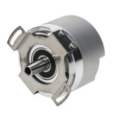
| Description | Absolute motor feedback encoder series for single-cable-solution, functional-safety applications. Singleturn and multiturn encoder for high-performance motion control, available as a non-safety, SIL2/PLd, or SIL3/PLe (category 3) design. |
| Key Features | Singleturn and multiturn encoder for high-performance motion control; functional safety applications (SIL2, PLd or SIL3, PLe, category 3); single cable solution with ACURO® link interface for 4-wire applications; input for motor winding temperature sensor; resolution up to 24 Bit ST + 12 Bit MT; wide operating temperature range; speed up to 7,000 rpm; encoder data stored in an “Electronic Data Sheet (EDS)” inside the encoder; motor and drive data can also be stored inside the encoder. |
| ● TECHNICAL DATA — MECHANICAL | |
| Housing Diameter | 58 mm. |
| Shaft | Shaft with integrated double-cardanic coupling hub. |
| Mounting Depth | 37 mm. |
| Mounting Flange | Direct flange mount (fixing screws M3). |
| Protection Class — Shaft Input | IP40. |
| Protection Class — Housing | IP40 (with mating connector). |
| Shaft Load incl. Coupling | Axial: 27 N max. Radial: 8.4 N max. |
| Speed | ≤ 7,000 rpm max. (see ambient temperature derating). |
| Starting Torque | typ. ≤ 3 Ncm. |
| Moment of Inertia | 5.15 x 10⁻⁶ kgm². |
| Angular Acceleration | 1.0 x 10⁵ rad/sec² max. |
| Vibration Resistance | 300 m/s² (10…2000 Hz) (DIN EN 60068-2-6). |
| Shock Resistance | ≤ 1,000 m/s² (6 ms) (DIN EN 60068-2-27). |
| Material — Shaft | Stainless Steel. |
| Material — Housing / Cover | Aluminum / Plastic. |
| Weight | approx. 230 g (ST or MT). |
| Connection (with Cable Guidance) | ECU Interface (axial); Temperature Sensor Interface (axial). |
| ● TECHNICAL DATA — TEMPERATURE CHARACTERISTICS | |
| Operating Temperature¹ | -20°C … +115°C. |
| Ambient Temperature² | -20°C … +105°C @ 6,000 rpm; -20°C … +100°C @ 7,000 rpm. |
| Storage Temperature³ | -30°C … +80°C. |
| ¹ See measuring point M1. ² See measuring point M2. ³ Due to packaging. | |
| ● TECHNICAL DATA — ELECTRICAL | |
| General Design | As per EN IEC 61010-1, protection class III, electrical contamination level 2, overvoltage class II. |
| Supply Voltage | 7 – 12 V DC. |
| Current w/o Load (typ.) | 12 V DC: < 130 mA. 7 V DC: < 190 mA. |
| Resolution — Single-turn | 24 Bit standard (others available on request). |
| Resolution — Multi-turn | 12 Bit. |
| Electrical Interface | 4-Wire: RS485. |
| Data Protocol | ACURO® link for Single Cable Solution. |
| Electronic Data Sheet (EDS) | 512 bytes of storage for encoder data. |
| OEM Memory | 7.5 kbytes of storage for motor and drive data. |
| Absolute Accuracy (max.) | ±20″ (at room temperature 23°C). |
| Repeatability (max.) | ±10″ (at room temperature 23°C). |
| ● TECHNICAL DATA — FUNCTIONAL SAFETY | |
| Design — AD58S | SIL2 according to EN IEC 61508, 62061, 61800-5-2, 61800-5-3; PLd according to EN ISO 13849-1. |
| Design — AD58E | SIL3 according to EN IEC 61508, 62061, 61800-5-2, 61800-5-3; PLe according to EN ISO 13849-1. |
| Resolution for Safe Position | 9 Bit Singleturn. |
| PFH-value | 1.05 x 10⁻⁹ per hour. |
| MTTFd | 846 years. |
| DCavg | 94.70%. |
| Realizable Safety Functions (per EN 61800-5-2) | SS1 (Safe Stop 1)¹; SS2 (Safe Stop 2)¹; SOS (Safe Operating Stop); SDI (Safe Direction); SLS (Safe Limited Speed); SLI (Safe Limited Increment); SLA (Safe Limited Acceleration); SSR (Safe Speed Range); SAR (Safe Acceleration Range). ¹Deceleration controlled (-d) or ramp monitored (-r). |
| ● ELECTRICAL CONNECTIONS | |
| ECU Interface | 4-pole, with mechanical lock. Pin 1 = UB+; Pin 2 = DATA+; Pin 3 = DATA−; Pin 4 = UB−. |
| Temperature Sensor Interface | 2-pole, with mechanical lock. Pin 1 = Sensor+ (KTY, PT1000); Pin 2 = Sensor− (KTY, PT1000). |
| Insulation Resistance | According to EN IEC 60204-1, PELV/SELV. |
| ● DIMENSIONAL DRAWINGS | |
| Housing / Flange | Housing Ø58 ±0.3 mm; flange radius R35 ±0.3 mm; shaft coupling hub Ø50.8 h7; mounting bolt circle Ø64 ±0.1 mm with 3 holes (Ø3.5 H11) at 3×120°, R29.1 ±0.2 mm radius (three-eared flange, marked M1). Mounting depth 37 ±0.7 mm (12 mm + 3 ±0.1 mm + 3 ±0.1 mm sections). Cable diameter: max. 4 mm (ECU interface side), max. 3 mm (temperature sensor interface side). Dimensions in mm. |
| Shaft Coupling Misalignment Tolerances (Encoder Shaft) | Axial misalignment max. ±0.3 mm; radial misalignment max. 0.05 mm; angular misalignment max. 0.2°. |
| ● ORDERING INFORMATION | |||||
| Type | Resolution | Supply Voltage | Flange, Protection, Shaft | Interface | Connection |
| AD58 / non safety AD58S = SIL2, PLd AD58E = SIL3, PLe | 0024 = 24 Bit ST 1224 = 24 Bit ST + 12 Bit MT | G = 7-12 VDC | Y.0V = Three-eared flange, IP40, shaft with integrated coupling hub | 4W = ACURO® link, 4 Wire | 9 = ECU Interface, axial, 4 pole + Temperature Sensor Interface, axial, 2 pole |
| ● ACCESSORIES — SHAFT COUPLING | |
| Coupling to Mate with AD58 Encoder Series | Part Nr. |
| For shaft size 6 mm | On request |
| For shaft size 12 mm | On request |
| For shaft size 14 mm | On request |
| Coupling dimensions: 20 mm length; Ø31 mm; 8 mm keyway/slot feature; bore Ø”A” sized to shaft. Other sizes available upon request. | |
| ● ACCESSORIES — MOTOR CONNECTION CABLES | |
| Description | Part Nr. |
| Encoder power/interface harness assembly, 30 cm, 4-pin AD58-Series connector on one end with cut wires on the opposite end | 1 572 019 |
| Temperature sensor harness assembly, 30 cm, 2-pin AD58-Series connector on one end and cut wires on the opposite end (for connection of motor winding temperature sensors — KTY, PT1000) | 1 572 020 |
| ● TECHNICAL MANUALS & SOFTWARE | |
| Item | Ordering Code |
| Implementation Guide and User Manual, English | 0 581 914 |
| Protocol description ACURO link, English | 2 572 040 |
| IP Core VHDL – ACURO link (for incorporation into drive) | On request |