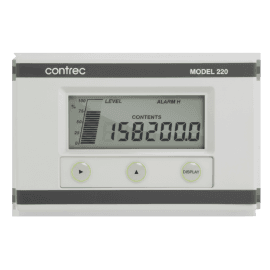
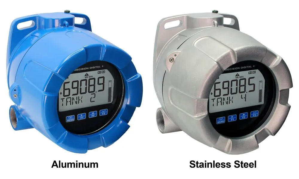
The Precision Digital ProtEX+ series of hazardous area indicators boasts loop-powered, explosion-proof, dust-ignition proof, and flame-proof certifications. They can display any 4-20 mA signal with a dual-line display that shows the process variable on the 5-character top display and the units of measure or tag on the 8-character bottom display. The feet and inches models display level in feet and inches on the top display and the bottom line displays a tag or custom message. The display also features a 20-segment bargraph.
These meters boast certifications from CSA for explosion-proof, dust-ignition proof, and flame-proof operations and from ATEX and IECEx as intrinsically safe. They can operate in temperatures as low as -40°C, but the display will not function in areas as cold as -55°C.
The four CapTouch buttons enable operation without removing the cover and can be set to normal or delayed modes or disabled for security. All models come with two open collector outputs and a digital input. Some models also feature two solid-state relays and isolated 4-20 mA analog output options. The open collector outputs act as alarm indicators and the digital input can acknowledge relays, start/stop a timer/stopwatch, and more. The relays can be programmed for alarm indication, on/off control, or pump alternation.
For programming and setup, Precision Digital offers a free PC-based software called MeterView XL that connects to the meter via a micro USB cable. The software simplifies the programming process and saves configuration files, while also powering the meter during programming.
For safe area versions of these instruments, click here.
Displays Level in Feet & Inches up to 999 Feet, 11 & 15/16 Inches (PD6907)
20-Segment Bargraph Standard
CapTouch Through-Window Button Programming with Normal and Delayed Modes
Loop-Powered Backlight with Red Backlight for Alarm Conditions
(2) Open Collector Outputs Standard; Assignable to Pulse, Alarm, Timer, or Stopwatch
(2) Optional Loop-Powered Solid-State Relays; Assignable to Alarm, Control, Timer, or Stopwatch
Stopwatch & Timer Functions to Drive Relays & Open Collectors
Optional Isolated 4-20 mA Analog Output
Relay Pump Alternation Based on Level and Runtime
Round Horizontal Tank Function; Just Enter Diameter & Length
32-Point Linearization, Square Root Extraction and Programmable Exponent Function
Free PC-Based MeterView XL USB Programming Software
Operating Temperature Range: -40 to 75°C (-40 to 167°F)
Installation Temperature Range: -55 to 75°C (-67 to 167°F)
Conformal Coated PCBs for Dust & Humidity Protection
CSA Certified for Explosion-Proof / Dust-Ignition Proof / Flame-Proof
ATEX and IECEx Certified as Intrinsically Safe
Explosion-Proof, IP68, NEMA 4X Die-Cast Aluminum & Stainless Steel Enclosures
3-Year Warranty
Except where noted all specifications apply to operation at +25°C.
Display
PD6907
Dual-line LCD with backlight. Top: 0.7″ (17.8 mm) 5 digits, 7-segment, FT-IN & fractions. Bottom: 0.4″ (10.2 mm), 8 alphanumeric 14-segment characters. Display may be programmed to turn red and flash a user-defined message on alarm condition.
PD6908
Dual-line LCD with backlight. Both lines alphanumeric. Top: 0.7″ (17.8 mm) 5 digits, 12-segment Bottom: 0.4″ (10.2 mm) 8 characters, 14-segment Display may be programmed to turn red and flash a user-defined message on alarm condition.
Backlight
Powered by 4-20 mA loop. Intensity varies with signal level.
Top Display
PD6907: FT – IN/*: Automatically reducing fractions to lowest denominator *FT-IN/16, FT-IN/8, FT-IN/4, FT-IN/2, FT-IN -99FT 11IN 15/16 to 999FT 11IN 15/16 PD6908: 5 digits (-9999 to 99999) or 5 characters (all capital & most lower-case letters)
Bottom Display
8 digits (-9,999,999 to 99,999,999; separated by commas) or 8 characters (all capital & most lower-case letters)
Bargraph
20 segments. Numeric percent indication at top (PD6907 only)
Decimal Point
Up to four decimal places on top display and up to seven decimal places on bottom display
Commas
Commas to indicate 1000s (e.g. 88,987,628) on bottom display only
Dual-Scale Feature
The input can be displayed in different scales on the top and bottom displays. For instance, the top display could display the input in height and the bottom display could display that same input in volume.
Alarm Indication
Programmable: loop-powered red backlight, flashing display, alarm symbol ⚠, bargraph segment flashes on alarm.
Custom Alarm Messages
Programmable for each relay/open collector: 8 characters maximum; displayed every 10 sec for 1 sec on bottom display. May be turned off.
Display Update Rate
Ambient > -10°C: 1 Update/Second Ambient = -20°C: 1 Update/2 Seconds From -20°C to -40°C the update rate slows down 1 second for every -2°C (e.g. at -24°C, 1 update/4 seconds).
Four CapTouch through-window buttons when cover is installed. The CapTouch buttons can be used with the cover removed. Free PC-based USB MeterView XL programming software.
Environmental
Operating temperature range: -40 to 75°C (-40 to 167°F) Storage temperature range: -55 to 85°C (-67 to 185°F) Installation temperature range: -55 to 75°C (-67 to 167°F) (The display ceases to function, however inputs and outputs continue to operate) Relative humidity: 0 to 90% non-condensing Printed circuit boards are conformally coated
Noise Filter
Averages the input signal over a period of time between 1 and 16 seconds to dampen the effects of a noisy signal that causes a jumpy display.
Filter Bypass
0.0 to 99.9% of full scale. Input signal changes greater than bypass value are displayed immediately.
Recalibration
Recalibration is recommended at least every 12 months.
Max/Min Display
Max/min readings reached by the process are stored until reset by the user or until power to the meter is turned off.
Tare
Tare function zeros out the meter to accommodate for weight of a container. Tare function can be assigned to a function key or a digital input.
Password
Programmable password restricts modification of programmed settings.
Non-Volatile Memory
All programmed settings are stored in non-volatile memory for a minimum of ten years if power is lost.
Normal Mode Rejection
64 dB at 50/60 Hz
Connections
Removable screw terminal blocks Display terminals: accept 16 to 30 AWG wire Relay terminals: accept 12 to 26 AWG wire 4-20 mA output: accept 16 to 30 AWG wire
Two ¾” NPT threaded conduit openings. M20 conduits are available. See Ordering Information for details.
Plug
Sold separately
Flange
Built-in flange for wall and pipe mounting.
Tamper-Proof Seal
Cover may be secured with tamper-proof seal.
ATEX & IECEx (ProtEX+ enclosure only)
Flameproof II 2GD Ex db IIC Gb Ex tb IIIC Db IP66/IP68 Tamb: -55°C to +85°C Certificate No.: Sira 19ATEX1252U Certificate No.: IECEx SIR 19.0075U
CSA (ProtEX+ enclosure only)
Class I, Division 1, Groups A, B, C, D Class II, Division 1, Group E, F, G Class III Ex db IIC Gb Ex tb IIIC Db Class I, Zone 1, AEx db IIC Gb Zone 21, AEx tb IIIC Db IP66/IP68/TYPE 4X Tamb: -55°C to +85°C Certificate No.: 80011200
UL (ProtEX+ enclosure only)
Class I, Division 1, Groups A, B, C, D Class II, Division 1, Groups E, F, G Class III Class I, Zone 1, AEx db IIC Gb Zone 21, AEx tb IIIC Ex db IIC Gb Ex tb IIIC Db IP66/IP68/TYPE 4X Tamb: -55°C to +85°C Certificate Number: E518920
Input
Input
4-20 mA
Accuracy
±0.02% of span ±1 count PD6908: Square root and programmable exponent: 10-100% FS
Voltage Drop
Without Backlight: 1.5 V maximum With backlight: 4.7 V maximum
Equivalent Resistance
With backlight off: 75 Ω @ 20 mA With backlight on: 235 Ω @ 20 mA
Input Overload
Over current protection to 1 A maximum, Over voltage protection to 30 VDC max (between mA+ and mA-/BL-)
Temperature Drift
25 PPM/°C from -40 to 75°C ambient
Function
PD6908: PV1: Linear (2-32 points), square root, or programmable exponent PV2: Linear (2-32 points) or round horizontal tank PD6907: PV1: Linear (2-32 points) PV2: Linear (2-32 points) or Round Horizontal Tank
Low-Flow / Low-Height Cutoff
Point below at which the display always shows zero. PD6908: 0.1 to 999,999 or disable. PD6907: 1/16 to 999FT 11IN 15/16 or disable.
HART Transparency
The meter does not interfere with existing HART communications; it displays the 4-20 mA primary variable and it allows the HART communications to pass through without interruption. The meter is not affected if a HART communicator is connected to the loop. The meter does not display secondary HART variables.
Common Open Collector & Relay Specifications
Number
Two open collectors & two relays
High or Low Alarm
User programmable for high or low alarm
Alarm Deadband
0-100% FS, user programmable
Output Assignment
Alarm, Timer, Stopwatch, or Disable
Alarm Output Source
Assign to PV (PV1, PV2) or Digital Input
On & Off Time Delay
0 to 9,999 seconds
Fail-Safe Operation
Independent for each open collector and relay. Fail-safe on, the output is on under normal conditions. Fail-safe off, the output is on under alarm conditions.
Alarm Operation
Automatic, automatic with manual override, latching (manual reset anytime), latching with reset after cleared (manual reset only after alarm has cleared)
Alarm Indication
Programmable: loop-powered red backlight, flashing display, alarm symbol ⚠, bargraph segment flashes on alarm.
Custom Alarm Messages
Programmable for each relay/open collector: 8 characters maximum; displayed every 10 sec for 1 sec on bottom display. May be turned off.
Alarm Acknowledge
CapTouch ACK button or external digital input resets output and screen indication.
Auto Initialization
When power is applied to the meter, open collectors and relays will reflect the state of the input to the meter.
Timer Output
One-shot or Continuous Off Time Delay: 1 sec to 99:59:59 (hrs:min:sec) On Time: 1 sec to 99:59:59 (hrs:min:sec)
Stopwatch
Output turns on when started and off when stopped.
Open Collector Outputs
Rating
Isolated open collector, sinking NPN 5-30 VDC @ 150 mA maximum
Output Assignment
Pulse, Alarm, Timer, Stopwatch on/off, or Disable
Pulse Output Source
PV (PV1, PV2) or Test Frequency
Pulse Output Factor
0.000001 to 999,999.9
Pulse Width
0.5 ms @ 1 kHz; 500 ms @ 1 Hz; 50% duty cycle
Pulse Output Frequency
1,000 Hz maximum
Quadrature Pulse Output
Available for Output 2 (90° behind Output 1) 500 Hz max
Alarm Output Source
Assign to PV (PV1, PV2) or Digital Input
Solid-State Relays
Rating
250 VAC/VDC @ 0.5 A resistive 38 VA; 250 VAC; 0.3 A pilot duty (inductive) 13 VA; 250 VDC; 0.3 A pilot duty (inductive)
Noise Suppression
Metal oxide varistors across outputs
Relay Assignment
Pump Alternation, Alarm, Timer, Stopwatch on/off, or Disable
Alarm Output Source
Assign to PV (PV1, PV2) or Digital Input
Pump Alternation
Relays may be programmed to alternate with each pump cycle with an elapsed time override where the pumps will alternate regardless of level. Pump alternation time can be programmed for 0 to 999:59 (hrs:min)
Relay (Pump) Runtime
Meter will keep track of how long each relay (pump) has operated and display this information.
Relay (Pump) Cycles
Meter will keep track of how many times the relays (pumps) have cycled and display this information.
4-20 mA Transmitter Output
Accuracy
±0.05% FS ±0.001mA
Output Source
PV1, PV2, re-transmit; reverse scaling allowed
Scaling Range
1.00 to 23.0 mA
Disable
High impedance state, less than 1 mA
Calibration
Factory calibrated 4.00 to 20.00 mA
Underrange
1.0 mA, 3.5 mA, or 3.8 mA (If input < 3.5 mA); or disable underrange; user selectable
Overrange
20.5 mA, 20.8 mA, or 23.0 mA (If input > 20.5 mA); or disable overrange; user selectable
Isolation
500 V input-to-output
Temperature Drift
0.5 μA/°C max from -40 to 75°C ambient
External Loop Power Supply
7.0 VDC to 30.0 VDC maximum
Output Loop Resistance
10-750 Ω @ 24 VDC; 10-1100 Ω @ 30 VDC
On-Board Digital Input
Function
Remote acknowledge/reset relays, reset max/min values, etc.
Contacts
2.1 VDC on contact. Connect normally open contacts across DI+ and DI-
Logic Levels
Logic High: 2.4 to 30 VDC (max) Logic Low: 0 to 0.9 VDC
Configure all parameters on the meter. Configure meters one at a time.
Configuration Files
Generate with or without meter connected; Save to file for later use.
USB Power Connection
Meter is powered by USB connection during programming, if 4-20 mA loop is not connected.
• The meter should only be connected to a computer while it is located in a safe area.
Compatibility
Programs created for Loop Leader and Loop Leader+ may be run on either meter. Programs created for VantageView+ and ProtEX+ can be run on either meter. No other program sharing is permissible.
General Compliance Information
Electromagnetic Compatibility
EMC Emissions
• CFR 47 FCC Part 15 Subpart B Class A emissions requirements (USA) • ICES-003 Information Technology emissions requirements (Canada) • AS/NZS CISPR 11 Group 1 Class A ISM emissions requirements (Australia/New Zealand) • EN 55011 Group 1 Class A ISM emissions requirements (EU) • EN 61000-6-4 Emissions requirements for Heavy Industrial Environments – Generic
EMC Emissions and Immunity
EN 61326-1 EMC requirements for Electrical equipment for measurement, control, and laboratory use – industrial use
Compliance Information
Hazardous Area Approvals
CSA
Explosion-proof for use in: Class I, Division 1, Groups B, C and D Dust-ignition proof for use in: Class II/III, Division 1, Groups E, F and G; T6 Flame-proof for use in: Zone 1, Ex d IIC T6 Ta = -55 to 75°C. Enclosure: Type 4X & IP66/IP68. Certificate number: 2325749
ATEX
II 1 G D Ex ia IIC T4 Ga Ex ia IIC T200°C Da Ta = -40 to 75°C Enclosure: Type 4X & IP66/IP68. Install per Control Drawing DW2636 (contained within LIM6908-2) Certificate number: CML 18ATEX2089X
IECEx
II 1 G D Ex ia IIC T4 Ga Ex ia IIC T200°C Da Ta = -40 to 75°C Enclosure: Type 4X & IP66/IP68. Install per Control Drawing DW2636 (contained within LIM6908-2) Certificate number: IECEx CML 18.0050X