Introducing the Precision Digital ProtEX-MAX PD8-765, a top-of-the-line explosion-proof process and temperature meter. This device combines the advanced features of the Trident X2 with full FM, CSA, ATEX, and IECEx explosion-proof certifications.
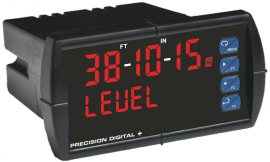
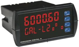
The PD8-765 boasts a large, 1.2″ (30.5 mm) display that is easy to read, even in bright sunlight, and can be seen from over 30 feet away. This makes it perfect for various industrial settings where visibility is crucial.
Key features of the PD8-765 include:
- Field programmable to accept multiple inputs: process voltage (0-5 V, 1-5 V), current (4-20 mA), 100 Ohm RTDs, and the four most common thermocouples.
- Adjustable display intensity to suit different lighting conditions, including direct sunlight.
- Convenient programming and operation without needing to open the housing, thanks to the SafeTouch® through-glass buttons and RS485 serial communication port with free Modbus® protocol.
Additionally, the PD8-765 offers options to enhance its functionality:
- Two relay outputs for alarms or control.
- A 4-20 mA output for integration with other systems.
- A 24 V transmitter power supply for powering external devices.
This explosion-proof indicator is ideal for professionals who need reliable and accurate measurements in hazardous environments. With its robust design and user-friendly features, the PD8-765 is a valuable tool for any industrial application.
General
Display: 1.20” (30.5 mm) red LED, 4 digits (-1999 to 9999)
Display Intensity: Eight user selectable intensity levels
Programming Methods: Four SafeTouch through-glass buttons when cover is installed. Four internal pushbuttons when cover is removed.
Noise Filter: Programmable 2 to 199 (0 will disable filter)
Display Update Rate: Process/RTD: 3.7-5/sec; TC: 1.8-2.5/sec
Overrange: Display flashes 9999
Underrange: Display flashes -1999
Recalibration: All inputs are calibrated at the factory; recalibration is recommended at least every 12 months.
Max/Min Display: Stored until reset by user or meter is turned off.
Password: Restricts modification of programmed settings.
Non-Volatile Memory: Settings stored for a minimum of 10 years.
Power Options: 85-265 VAC, 50/60 Hz; 90-265 VDC, 20 W max or 12-36 VDC; 12-24 VAC, 6 W max.
Required Fuse: UL Recognized, 5 A max, slow-blow; up to 6 meters may share one fuse.
Normal Mode Rejection: 64 dB at 50/60 Hz
Isolation: 4 kV input/output-to-power line; 500 V input-to-output or output-to-24 VDC supplies.
-6X5 skus only: 100 V output-to-24 VDC supply
Environmental:
T6 Class operating temperature range Ta = -40 to 60°C
T5 Class operating temperature range Ta = -40 to 65°C
Connections:
Power & Signal: removable screw terminal blocks accept 12 to 22 AWG.
Serial: RJ11 header, standard on all meters.
Enclosure: Explosion-proof die cast aluminum with glass window, corrosion resistant epoxy coating, color: blue. NEMA 4X, 7, & 9, IP68. Default conduit connections: Four ¾” NPT threaded conduit openings and two ¾” NPT metal conduit plugs with 12 mm hex key fitting installed. Additional conduit opening configurations may be available; verify quantity and sizes on specific device labeling during installation.
Dimensions: 6.42″ x 7.97″ x 8.47″ (W x H x D) (163 mm x 202 mm x 215 mm)
Weight: 16.0 lbs (7.26 kg)
Warranty: 3 years parts & labor
Process Inputs
Inputs: Field selectable: 0-20 mA, 4-20 mA, 1-5 V, ±10 V
Accuracy: ±0.05% FS ±1 count; square root: ±0.1% FS ±2 counts
Function: Linear or square root
Low-Flow Cutoff: 0 to 9999 (0 disables cutoff function)
Decimal Point: Up to 3 decimals: d.ddd, dd.dd, ddd.d, or dddd
Calibration: Scale without signal or calibrate with signal source
Calibration Range: User programmable over entire range of meter
Input Impedance: Voltage range: greater than 1 M Ω, Current Range: 50-100 Ω, varies with resettable fuse impedance
Input Overload: Protected by automatically resettable fuse
HART Transparency: Analog input will not interfere with existing HART communications on the wired 4-20 mA signal
Temperature Drift:
0 to 65°C ambient-40 to 0°C ambientCurrent: ±0.20% FS (50 PPM/°C)Current: ±0.80% FSVoltage: ±0.02% FS (1.7 PPM/°C)Voltage: ±0.06% FS
Transmitter Supply: Isolated, one or two transmitter supplies
P1: 24 VDC ±10% @ 200 mA max (-1 option)
P1 & P2: 24 VDC ±10% @ 200 mA & 40 mA max (-2 option)
Temperature Inputs
Inputs: Factory calibrated, field selectable: type J, K, T, or E thermocouples and 100 Ω platinum RTD (0.00385 or 0.00392 curve)
Resolution: 1°; type T: 1° or 0.1°
Cold Junction Reference: Automatic
Temperature Drift: ±2°C maximum
Offset Adjustment: Programmable to ±19.9°. This parameter allows the user to apply an offset value to the temperature being displayed.
Input Impedance: Greater than 100 k Ω
Sensor Break: All relays and alarm status LEDs go to alarm state.
Input TypeRangeAccuracy
(0-65° C)Accuracy
(-40-0° C)Type J-58° to 1382° F
-50° to 750° C±2° F
±1° C±5° F
±3° CType K-58° to 2300° F
-50° to 1260° C±2° F
±1° C±4° F
±2° CType T-292° to 700° F
-180° to 371° C±2° F
±1° C±13° F
±7° CType T
0.1° Res-199.9° to 700.0° F
-180.0° to 371.0° C±1.8° F
±1° C±13° F
±7.2° CType E-58° to 1578° F
-50° to 870° C±2° F
±1° C±11° F
±6° C100 Ω RTD-328° to 1382° F
-200° to 750° C±1°F
±1° C±5°F
±3° C
Relays
Rating: 2 Form C (SPDT); rated 3 A @ 30 VDC or 3 A @ 250 VAC resistive load; 1/14 HP @ 125/250 VAC inductive loads
Deadband: 0-100% FS, user selectable
High or Low Alarm: User may program any alarm for high or low
Relay Operation:
- Automatic (non-latching)
- Latching
- Pump alternation control
Relay Reset: User selectable via front panel buttons or PC
- Automatic reset only (non-latching)
- Automatic plus manual reset at any time (non-latching)
- Manual reset only, at any time (latching)
- Manual reset only after alarm condition has cleared (latching).
Automatic Reset: Relays reset when input passes the reset point
Manual Reset: Front panel button, MeterView, Modbus registers
Time Delay: 0 to 199 seconds, on and off delays; programmable
Fail-Safe Operation: Programmable, independent for each relay. Relay coils are energized in non-alarm condition. In case of power failure; relays will go to alarm state.
Auto Initialization: When power is applied to the meter, relays will reflect the state of the input to the meter.
Isolated 4-20 mA Transmitter Output
Scaling Range: 1.00 to 23.00 mA; reverse scaling allowed.
Calibration: Factory calibrated 4.00 to 20.00 mA
Accuracy: ±0.1% FS ±0.004 mA
Temperature Drift: 50 PPM/°C
Note: Analog output drift is separate from input drift
Isolation: 500 V input-to-output or output-to-24 VDC supplies; 4 kV output-to-power line
External Power: 35 VDC maximum
Output Loop Resistance:
Loop ResistancePower SupplyMinimumMaximum24 VDC10 Ω700 Ω35 VDC (external)100 Ω1200 Ω
Serial Communications
Compatability: EIA-485
Connectors: Removable screw terminal connector
Max Distance: 3,937′ (1,200 m) max
Status Indication:Separate LEDs for Power (P), Transmit (TX), and Receive (RX)
Protocol: Two selectable. PDC protocol (for use with MeterView) and Modbus RTU
Meter Address: PDC protocol: 0 to 99, Modbus protocol: 1 to 247
Baud Rate: 300 to 19,200 bps
Transmit Time Delay: Programmable 0 to 199 ms or transmitter always on for RS-422 communications.
Data: 8 bit (1 start bit, 1 stop bit)
Parity: None (2 stop bits), even, or odd
(Modbus only; PDC protocol does not use parity)
Byte-to-Byte Timeout: 0.01 to 2.54 seconds (Modbus only)
Turn Around Delay: Less than 2 ms (fixed)
Note: Both downloadable protocol register tables can be found in the documentation list below.
External Switch Contacts
Open State: +5 VDC open contact on switch input terminals
Closed State: Closed contact switch input terminal to common/ground, active low 0 to 0.4 VDC, or open collector transistor activated input
Product Ratings and Approvals
FM Enclosure: Type 4X; IP66
Class I, Division 1, Groups B, C, D
Class II, Division 1, Groups E, F, G
Class III, Division 1, T5/T6
Class I, Zone 1, AEx d, IIC Gb T5/T6
Zone 21, AEx tb IIIC T90°C; Ta -40°C to +65°C
T6 Ta = -40°C to +60°C; T5 Ta = -40°C to +65°C
Certificate Number: 3047283
CSA: Class I, Division 1, Groups B, C, D
Class II, Division 1, Groups E, F, G
Class III, Division 1
Class I Zone 1 Ex d IIC
Zone 21 Ex tb IIIC T90°C
-40°C < Tamb. < +60° C; Temperature Code T6
-40°C < Tamb. < +65° C; Temperature Code T5
Enclosure Type 4X & IP66
Certificate Number: 2531731
ATEX: II 2 G D Ex d IIC T* Gb
Ex tb IIIC T90°C Db IP68
Ta = -40°C to +*°C
*T6 = -40°C to +60°C
*T5 = -40°C to +65°C
Certificate number: Sira 12ATEX1182
IECEx: Ex d IIC T* Gb
Ex tb IIIC T90°C Db IP68
Ta = -40°C to +*°C
*T6 = -40°C to +60°C
*T5 = -40°C to +65°C
Certificate Number: IECEx SIR 12.0073
MeterView® for Trident
MeterView software allows remote programming and data acquisition of the Trident series. The remote programming allows for all available meter settings to be programmed from a personal computer through an easy user-friendly interface. The data acquisition allows the user to gather readings from up to 100 meters at user-selected intervals and generate charts using common tools like Microsoft® Excel.
Digital Panel Meters make a great front end to a PC-based data acquisition system. They are easy to set up, can be used for a wide range of inputs, will power the transmitter, and best of all provide a local display of the process. Precision Digital has the perfect package with its Trident Digital Panel Meters, a wide selection of serial adapters and converters and free MeterView software. Data is displayed on the PC and written to a file that could then be imported into a spreadsheet or other application.
Data Logging up to 100 Trident Meters

Sample File Generated by MeterView®
Great for tank level monitoring!
Ordering Example: System consisting of 10 Tridents & MeterView
QtyskuDescription10PD765-6R2-10Trident with 2 Relays & 24 VDC Transmitter Supply10PDA7422Trident RS-485 Serial Adapter1PDA8485-IUSB to RS-422/485 Isolated Converter1PDA7503-2MeterView Software for 1-10 Meters
Dimensions

Application
Pump Alternation

