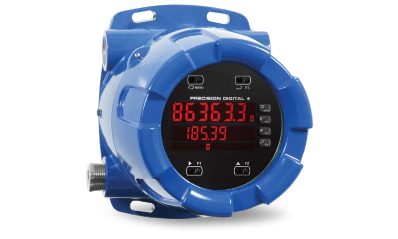
Ensure accurate flow monitoring in challenging environments with the Precision Digital PD8-6363 Flow Rate Totalizer. This explosion-proof device is certified by FM, CSA, ATEX, and IECEx, making it a vital tool for various industrial applications that require pulse output flowmeters.
Key Features for Superior Performance
The PD8-6363 is packed with features that cater to the needs of today’s industrial processes:
Dual-Line Display: The device features a dual-line, 6-digit Sunbright display that is easy to read, even in sunlight. It allows you to monitor flow rates and totals from two pulse output flowmeters at the same time.
Flexible Display Options: You can display flow rates simultaneously, alternate between two inputs, or perform calculations on flow rates and totals, depending on your monitoring needs.
Total Overflow Capability: The PD8-6363 supports totals of up to 9 digits, ensuring accurate data display for high-volume applications.
Internal Relays and Analog Output: This device can include up to four internal relays and a 4-20 mA analog output, offering additional control and integration options for your processes.
SafeTouch® Technology: With SafeTouch® through-glass buttons, you can easily program and operate the device without opening the housing, making adjustments simple and safe.
RS485 Serial Communication: The PD8-6363 includes an RS485 serial communication port with a free Modbus® protocol, allowing for easy remote programming and monitoring to boost operational efficiency.
Dependable Performance in Hazardous Conditions
Built to endure the challenges of hazardous environments, the Precision Digital PD8-6363 Flow Rate Totalizer provides reliable and precise performance. Its explosion-proof design meets the highest safety standards, giving you confidence in your flow monitoring tasks.
Discover Precision Monitoring Today
Unlock the potential of the Precision Digital PD8-6363 Flow Rate Totalizer for your industrial needs. With its advanced features, sturdy construction, and approvals for hazardous locations, it delivers exceptional performance and reliability for accurate flow monitoring in demanding settings.
General
Display: Upper display: 0.60″ (15 mm) high. Lower display: 0.46″ (12 mm) high. 6 digits each (-99999 to 999999), red LEDs with lead zero blanking.
Display Intensity: Eight user selectable intensity levels
Display Update Rate: 10 per second; up to 1 per 100 seconds (and is a function of Low Gate setting); Total: 10 per second (fixed)
Overrange: Display flashes 999999
Underrange: Display flashes -99999
Display Assignment: The Upper and Lower displays may be assigned to show various parameters including rate channels, totals, grand totals, math functions, Modbus input, and more.
Programming Methods: Four through-glass SafeTouch buttons, four mechanical buttons behind glass, digital inputs, PC and MeterView Pro software, or Modbus registers.
F4 Digital Input Contacts: 3.3 VDC on contact. Connect normally open contacts across F4 to COM.
F4 Digital Input Logic Levels: Logic High: 3 to 5 VDC; Logic Low: 0 to 1.25 VDC
Max/Min Display: Max/min readings reached by the process are stored until reset by the user or until power to the meter is cycled.
Password: Three programmable passwords restrict modification of programmed settings and two prevent resetting the totals.
Non-Volatile Memory: All programmed settings are stored in non-volatile memory for a minimum of ten years if power is lost.
Recalibration: All ranges are calibrated at the factory. Recalibration is recommended at least every 12 months.
Power Options: 85-265 VAC 50/60 Hz, 90-265 VDC, 20 W max, or optional sku with 12-24 VDC ±10%, 15 W max.
Fuse: Required external fuse: UL Recognized, 5 A max, slow blow; up to 6 meters may share one 5 A fuse.
Isolated Transmitter Power Supply: Terminals P+ & P-: 24 VDC ± 10%. Isolated from the input at >500 V. Jumper selectable for 24, 10, or 5 VDC supply (internal jumper J4). All skus transmitter supply rated @ 25mA max.
Isolation: 4 kV input/output-to-power line. 500 V input-to-output or output-to-P+ supply.
Overvoltage Category: Installation Overvoltage Category II: Local level with smaller transient overvoltages than Installation Overvoltage Category III.
Environmental: T6 Class operating temperature range Ta = -40 to 60°C; T5 Class operating temperature range Ta = -40 to 65°C.
Max Power Dissipation: Maximum power dissipation limited to 15.1 W.
Connections: Removable screw terminal blocks accept 12 to 22 AWG wire, RJ45 for external relays, digital I/O, and serial communication adapters.
Enclosure: Explosion-proof die cast aluminum with glass window, corrosion resistant epoxy coating, color: blue. NEMA 4X, 7, & 9, IP68. Default conduit connections: Four ¾” NPT threaded conduit openings and two ¾” NPT metal conduit plugs with 12 mm hex key fitting installed. Additional conduit opening configurations may be available; verify quantity and sizes on specific device labeling during installation.
Mounting: Four slotted flanges for wall mounting or NPS 1½” to 2½” or DN 40 to 65 mm pipe mounting.
Dimensions: 6.42″ x 7.97″ x 8.47″ (W x H x D) (163 mm x 202 mm x 215 mm)
Weight: 16.0 lbs (7.26 kg)
Warranty: 3 years parts & labor
USB Connection: Compatibility: USB 2.0 Standard, Compliant. Connector Type: Micro-B receptacle. Cable: USB A Male to Micro-B Cable. Driver: Windows 98/SE, ME, 2000, Server 2003/2008, XP 32/64-Bit, Vista 32/64-Bit, Windows 7 32/64-Bit, Windows 10 32/64-Bit. Power: USB Port
Dual Input Functionality
Pulse Inputs: Two, Field selectable: Pulse or square wave 0-5 V, 0-12 V, or 0-24 V @ 30 kHz; TTL; open collector 4.7 kΩ pull-up to 5 V @ 30 kHz; NPN or PNP transistor, switch contact 4.7Ω kpull-up to 5 V @ 40 Hz; Modbus PV (Slave) Channels: Channel A, Channel B, Channel C (Math channel)
Programmable Constants: Constant P (Adder): -99.999 to 999.999, default: 0.000, Constant F (Factor): 0.001 to 999.999, default: 1.000
Sequence of Operations for Input Programming: Detailed sequence for setting up various parameters for input channels.
Low Voltage Mag Pickup: Sensitivity: 40 mVp-p to 8Vp-p
Minimum/Maximum Input Frequency: Detailed specifications for minimum and maximum input frequency.
Accuracy: ±0.03% of calibrated span ±1 count
Temperature Drift: Detailed specifications for temperature drift.
Multi-Point Linearization: 2 to 32 points for channel A and B
Low-Flow Cutoff: 0-999999 (0 disables cutoff function)
Decimal Point: Up to five decimal places or none: d.ddddd,
Applications
Differential Pressure Flow (PD6262)
The PD8-6262 can display flow rate and total by extracting the square root from the 4-20 mA signal from differential pressure transmitters. The user-selectable low-flow cutoff feature gives a reading of zero when the flow rates drop below a user-selectable value.
- Display Flow Rate
- User Selectable Low-Flow Cutoff
- Only 2 Calibration Points Required
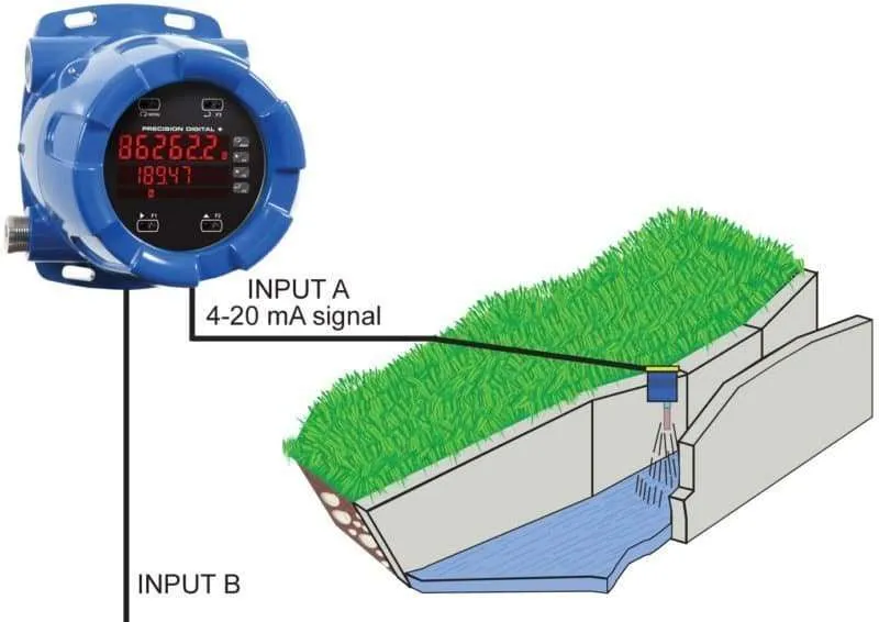
Open Channel Flow (PD6262)
The PD8-6262, in combination with ultrasonic level transmitters, makes for an easy and convenient way to measure and display open channel flow rates and totals in most weirs and flumes, and take periodic samples. All the user needs to do is enter the exponents for the weirs or flumes into the PD8-6262 and the PD8-6262 automatically raises the input signals to those powers. Sampling can be based on the total flow or the flow rate. Each channel’s signal input conditioning is programmed independently.

Weir Flow Calculated Using Exponential Signal Input Conditioning
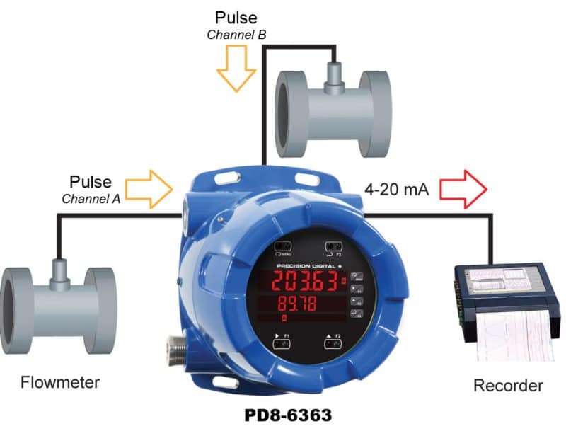
Convert Pulse to 4-20 mA (PD6363)
The PD8-6363 accepts pulse outputs from flowmeters and with the appropriate option installed, can convert the pulses to a 4-20 mA signal. The 4-20 mA signal can be programmed to correspond to either the flow rate or the total flow.
- Use K-Factor or Multi-Point Scaling
- ProVu Powers the Flowmeter
- Up to 3 Analog Outputs

MeterView® Pro Software
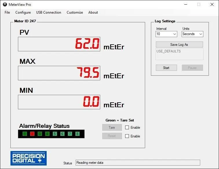
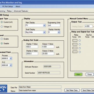
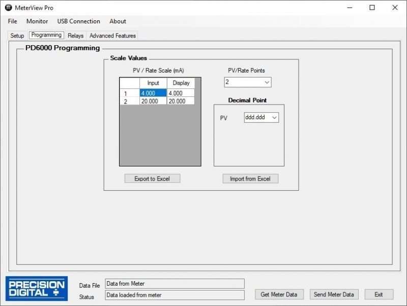
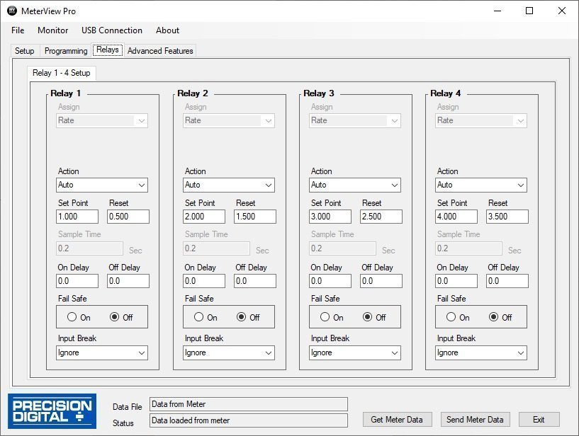
 MeterView® Pro software is designed for use with ProVu, ProtEX-MAX, or Helios Series meters and allows users to remotely program, monitor, and datalog using a PC. Remote programming allows for all available meter settings to be programmed through an easy, user-friendly interface. The data acquisition feature allows the user to gather readings from a meter at user-selected intervals and generate charts using common tools like Microsoft® Excel. A linearization setup function is also included. With this utility the user can configure up to 32 linearization points and upload them to the meter. All configuration data can be saved to a file for future use.
This software is accessible via the onboard USB connection on all Helios large display meters, ProVu panel meters, and ProVu-based ProtEX-MAX explosion-proof meters produced since 6 September 2016 (firmware version 4.0 or higher). In order for meters produced prior to 6 September 2016 (firmware version 3.1 or lower) to establish digital communications with a PC, a serial communications adapter is required. For an RS-232 connection, use a PDA1232 adapter.
To determine the software version of a meter:
- Go to the Diagnostics menu (
 ) and press Enter button.
 - Press Up arrow button and scroll to Information menu (Info).
- Press Enter to access the software number (), version (), and serial number () information. Write down the information as it is displayed. Continue pressing Enter until all the information is displayed.
- The meter returns to Run Mode after displaying all the settings.
Monitor and Datalog

Setup

Programming

Relays

 MeterView® Pro software is designed for use with ProVu, ProtEX-MAX, or Helios Series meters and allows users to remotely program, monitor, and datalog using a PC. Remote programming allows for all available meter settings to be programmed through an easy, user-friendly interface. The data acquisition feature allows the user to gather readings from a meter at user-selected intervals and generate charts using common tools like Microsoft® Excel. A linearization setup function is also included. With this utility the user can configure up to 32 linearization points and upload them to the meter. All configuration data can be saved to a file for future use.