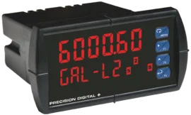
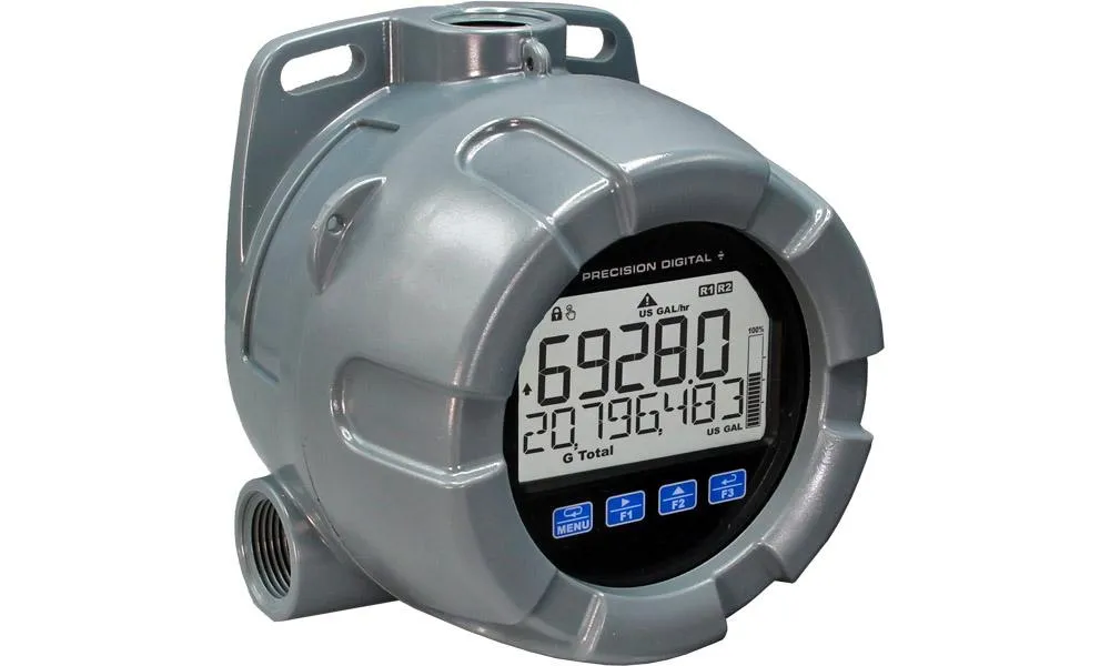
Introducing the VantageView+ Loop-Powered Meters, your go-to solution for dependable performance in tough environments. These meters not only offer advanced display features but also provide excellent control options. They are perfect for accurately displaying 4-20 mA signals with ease. Let’s take a closer look at what makes these meters stand out:
Clear and Enhanced Display:
- The dual-line display ensures you can easily see process variables along with their units or tags.
- Some models come with a special level display that shows measurements in feet and inches for your convenience.
- A customizable 20-segment bargraph adds to the clarity of data visualization.
User-Friendly Operation:
- With four CapTouch buttons, you can operate the meters without needing to open the cover.
- These buttons support both normal and delayed modes, and you can disable them for extra security.
Flexible Output and Input Options:
- Every model comes with open collector outputs and a digital input.
- Options include two solid-state relays and an isolated 4-20 mA analog output.
- Use the open collector outputs for alarm signals, while the digital input allows for relay acknowledgment and timer/stopwatch functions.
- The relays can be programmed for alarms, on/off control, or pump alternation.
Easy Programming:
- Connect to the MeterView XL software via a micro USB cable for straightforward meter programming and setup.
- This software simplifies the programming process and lets you create saved configuration files.
- You can power the meter through the USB connection while programming, so there’s no need for extra power sources.
Discover the reliability and ease of use with VantageView+ Loop-Powered Meters. With their advanced display features and versatile control options, these meters are designed to perform in harsh conditions while ensuring effortless operation and efficient programming.
Except where noted all specifications apply to operation at +25°C.
Display
PD6907 | Dual-line LCD with backlight.
Top: 0.7″ (17.8 mm) 5 digits, 7-segment, FT-IN & fractions.
Bottom: 0.4″ (10.2 mm), 8 alphanumeric 14-segment characters.
Display may be programmed to turn red and flash a user-defined message on alarm condition. |
PD6908 | Dual-line LCD with backlight.
Both lines alphanumeric.
Top: 0.7″ (17.8 mm) 5 digits, 12-segment
Bottom: 0.4″ (10.2 mm) 8 characters, 14-segment
Display may be programmed to turn red and flash a user-defined message on alarm condition. |
Backlight | Powered by 4-20 mA loop. Intensity varies with signal level. |
Top Display | PD6907:
FT – IN/*: Automatically reducing fractions to lowest denominator
*FT-IN/16, FT-IN/8, FT-IN/4, FT-IN/2, FT-IN
-99FT 11IN 15/16 to 999FT 11IN 15/16
PD6908:
5 digits (-9999 to 99999) or 5 characters
(all capital & most lower-case letters) |
Bottom Display | 8 digits (-9,999,999 to 99,999,999; separated by commas) or 8 characters
(all capital & most lower-case letters) |
Bargraph | 20 segments.
Numeric percent indication at top (PD6907 only) |
Decimal Point | Up to four decimal places on top display and up to seven decimal places on bottom display |
Commas | Commas to indicate 1000s
(e.g. 88,987,628) on bottom display only |
Dual-Scale Feature | The input can be displayed in different scales on the top and bottom displays. For instance, the top display could display the input in height and the bottom display could display that same input in volume. |
Alarm Indication | Programmable: loop-powered red backlight, flashing display, alarm symbol ⚠, bargraph segment flashes on alarm. |
Custom Alarm Messages | Programmable for each relay/open collector: 8 characters maximum; displayed every 10 sec for 1 sec on bottom display. May be turned off. |
Display Update Rate | Ambient > -10°C: 1 Update/Second
Ambient = -20°C: 1 Update/2 Seconds
From -20°C to -40°C the update rate slows down
1 second for every -2°C (e.g. at -24°C, 1 update/4 seconds). |
Overrange | PD6907: Top: 999 11 15/16
PD6908: Top: 99999
Bottom: 99,999,999 (flashing) |
Underrange | PD6907: Top -99 11 15/16
PD46908: Top: -9999
Bottom: -9,999,999 (flashing) |
General
Programming Method | Four CapTouch through-window buttons when cover is installed.
The CapTouch buttons can be used with the cover removed.
Free PC-based USB MeterView XL programming software. |
Environmental | Operating temperature range: -40 to 75°C (-40 to 167°F)
Storage temperature range: -40 to 85°C (-40 to 185°F)
Installation temperature range: -40 to 75°C (-40 to 167°F)
Relative humidity: 0 to 90% non-condensing
Printed circuit boards are conformally coated |
Noise Filter | Averages the input signal over a period of time between 1 and 16 seconds to dampen the effects of a noisy signal that causes a jumpy display. |
Filter Bypass | 0.0 to 99.9% of full scale. Input signal changes greater than bypass value are displayed immediately. |
Recalibration | Recalibration is recommended at least every 12 months. |
Max/Min Display | Max/min readings reached by the process are stored until reset by the user or until power to the meter is turned off. |
Tare | Tare function zeros out the meter to accommodate for weight of a container. Tare function can be assigned to a function key or a digital input. |
Password | Programmable password restricts modification of programmed settings. |
Non-Volatile Memory | All programmed settings are stored in non-volatile memory for a minimum of ten years if power is lost. |
Normal Mode Rejection | 64 dB at 50/60 Hz |
Connections | Removable screw terminal blocks
Display terminals: accept 16 to 30 AWG wire
Relay terminals: accept 12 to 26 AWG wire
4-20 mA output: accept 16 to 30 AWG wire |
Tightening Torque | Display terminals: 2.5 lb-in (0.28 Nm)
Relay terminals: 4.5 lb-in (0.5 Nm)
4-20 mA output terminals: 2.5 lb-in (0.28 Nm) |
Overall Dimensions | 5.25″ x 5.65″ x 4.18″ (133 x 144 x 106 mm) (W x H x D) |
Weight | 1.9 lbs (0.9 kg) |
Warranty | 3 years parts and labor. |
Enclosure
Material | Polycarbonate plastic with UV stabilizer |
Gasket | Buna-N |
Rating | NEMA 4X, IP66 plastic, UL 94V-0 |
Color | Grey |
Window | Clear polycarbonate with UV stabilizer |
Conduits | Three 3/4″ NPT threaded conduit openings |
Plug | Two 3/4″ NPT plastic conduit plugs with 1.29″ wrenching flats and a screwdriver slot are included |
Flange | Built-in flange for wall and pipe mounting. |
Tamper-Proof Seal | Cover may be secured with tamper-proof seal. |
Input
Input | 4-20 mA |
Accuracy | ±0.02% of span ±1 count
PD6908: Square root and programmable exponent: 10-100% FS |
Voltage Drop | Without Backlight: 1.5 V maximum
With backlight: 4.7 V maximum |
Equivalent Resistance | With backlight off: 75 Ω @ 20 mA
With backlight on: 235 Ω @ 20 mA |
Input Overload | Over current protection to 1 A maximum, Over voltage protection to 30 VDC max (between mA+ and mA-/BL-) |
Temperature Drift | 25 PPM/°C from -40 to 75°C ambient |
Function | PD6908:
PV1: Linear (2-32 points), square root, or programmable exponent
PV2: Linear (2-32 points) or round horizontal tank
PD6907:
PV1: Linear (2-32 points)
PV2: Linear (2-32 points) or Round Horizontal Tank |
Low-Flow / Low-Height Cutoff | Point below at which the display always shows zero.
PD6908: 0.1 to 999,999 or disable.
PD6907: 1/16 to 999FT 11IN 15/16 or disable. |
HART Transparency | The meter does not interfere with existing HART communications; it displays the 4-20 mA primary variable and it allows the HART communications to pass through without interruption.
The meter is not affected if a HART communicator is connected to the loop. The meter does not display secondary HART variables. |
Common Open Collector & Relay Specifications
Number | Two open collectors & two relays |
High or Low Alarm | User programmable for high or low alarm |
Alarm Deadband | 0-100% FS, user programmable |
Output Assignment | Alarm, Timer, Stopwatch, or Disable |
Alarm Output Source | Assign to PV (PV1, PV2) or Digital Input |
On & Off Time Delay | 0 to 9,999 seconds |
Fail-Safe Operation | Independent for each open collector and relay.
Fail-safe on, the output is on under normal conditions.
Fail-safe off, the output is on under alarm conditions. |
Alarm Operation | Automatic, automatic with manual override, latching (manual reset anytime), latching with reset after cleared (manual reset only after alarm has cleared) |
Alarm Indication | Programmable: loop-powered red backlight, flashing display, alarm symbol ⚠, bargraph segment flashes on alarm. |
Custom Alarm Messages | Programmable for each relay/open collector: 8 characters maximum; displayed every 10 sec for 1 sec on bottom display. May be turned off. |
Alarm Acknowledge | CapTouch ACK button or external digital input resets output and screen indication. |
Auto Initialization | When power is applied to the meter, open collectors and relays will reflect the state of the input to the meter. |
Timer Output | One-shot or Continuous
Off Time Delay: 1 sec to 99:59:59 (hrs:min:sec)
On Time: 1 sec to 99:59:59 (hrs:min:sec) |
Stopwatch | Output turns on when started and off when stopped. |
Open Collector Outputs
Rating | Isolated open collector, sinking NPN
5-30 VDC @ 150 mA maximum |
Output Assignment | Pulse, Alarm, Timer, Stopwatch on/off, or Disable |
Pulse Output Source | PV (PV1, PV2) or Test Frequency |
Pulse Output Factor | 0.000001 to 999,999.9 |
Pulse Width | 0.5 ms @ 1 kHz; 500 ms @ 1 Hz; 50% duty cycle |
Pulse Output Frequency | 1,000 Hz maximum |
Quadrature Pulse Output | Available for Output 2
(90° behind Output 1) 500 Hz max |
Alarm Output Source | Assign to PV (PV1, PV2) or Digital Input |
Solid-State Relays
Rating | 250 VAC/VDC @ 0.5 A resistive
38 VA; 250 VAC; 0.3 A pilot duty (inductive)
13 VA; 250 VDC; 0.3 A pilot duty (inductive) |
Noise Suppression | Metal oxide varistors across outputs |
Relay Assignment | Pump Alternation, Alarm, Timer, Stopwatch on/off, or Disable |
Alarm Output Source | Assign to PV (PV1, PV2) or Digital Input |
Pump Alternation | Relays may be programmed to alternate with each pump cycle with an elapsed time override where the pumps will alternate regardless of level. Pump alternation time can be programmed for 0 to 999:59 (hrs:min) |
Relay (Pump) Runtime | Meter will keep track of how long each relay (pump) has operated and display this information. |
Relay (Pump) Cycles | Meter will keep track of how many times the relays (pumps) have cycled and display this information. |
4-20 mA Transmitter Output
Accuracy | ±0.05% FS ±0.001mA |
Output Source | PV1, PV2, re-transmit; reverse scaling allowed |
Scaling Range | 1.00 to 23.0 mA |
Disable | High impedance state, less than 1 mA |
Calibration | Factory calibrated 4.00 to 20.00 mA |
Underrange | 1.0 mA, 3.5 mA, or 3.8 mA (If input < 3.5 mA); or disable underrange; user selectable |
Overrange | 20.5 mA, 20.8 mA, or 23.0 mA (If input > 20.5 mA); or disable overrange; user selectable |
Isolation | 500 V input-to-output |
Temperature Drift | 0.5 μA/°C max from -40 to 75°C ambient |
External Loop Power Supply | 7.0 VDC to 30.0 VDC maximum |
Output Loop Resistance | 10-750 Ω @ 24 VDC; 10-1100 Ω @ 30 VDC |
On-Board Digital Input
Function | Remote acknowledge/reset relays, reset max/min values, etc. |
Contacts | 2.1 VDC on contact. Connect normally open contacts across DI+ and DI- |
Logic Levels | Logic High: 2.4 to 30 VDC (max)
Logic Low: 0 to 0.9 VDC |
MeterView XL Programming Software
Availability | Free download from www.predig.com/meterviewxl |
System Requirements | Microsoft® Windows® 7 & 10 |
Communications | USB 2.0 (Standard USB A to USB B) Cable provided |
Configuration | Configure all parameters on the meter. Configure meters one at a time. |
Configuration Files | Generate with or without meter connected; Save to file for later use. |
USB Power Connection | Meter is powered by USB connection during programming, if 4-20 mA loop is not connected. |
 |
• The meter should only be connected to a computer while it is located in a safe area. |
Compatibility | Programs created for Loop Leader and Loop Leader+ may be run on either meter. Programs created for VantageView+ and ProtEX+ can be run on either meter. No other program sharing is permissible. |
General Compliance Information
Electromagnetic Compatibility
EMC Emissions | • CFR 47 FCC Part 15 Subpart B Class A emissions requirements (USA)
• ICES-003 Information Technology emissions requirements (Canada)
• AS/NZS CISPR 11 Group 1 Class A ISM emissions requirements (Australia/New Zealand)
• EN 55011 Group 1 Class A ISM emissions requirements (EU)
• EN 61000-6-4 Emissions requirements for Heavy Industrial Environments – Generic |
EMC Emissions and Immunity | EN 61326-1
EMC requirements for Electrical equipment for measurement, control, and laboratory use – industrial use |