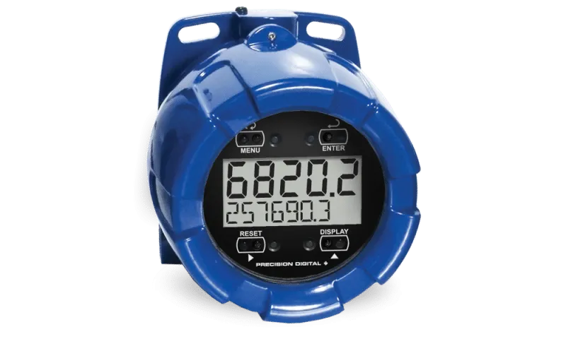
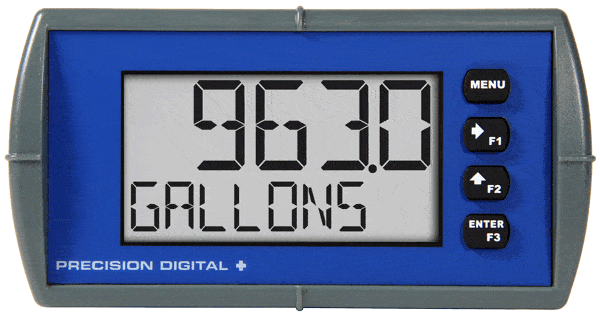
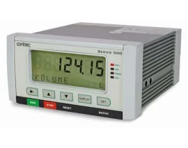
Introducing the Precision Digital ProtEX-RTA PD6820, a reliable explosion-proof flow rate and totalizer designed for safety and efficiency. This device can easily display both flow rate and total from a 4-20 mA analog output flowmeter.
One of the key benefits of the PD6820 is that it is loop-powered. This means you won’t need to install extra power lines in hazardous areas, saving you time and money.
The PD6820 features:
- A five-digit upper display for flow rate.
- A seven-character lower display for total.
- A standard backlight for easy reading in low light conditions.
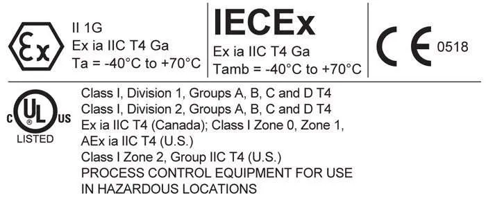
Like all ProtEX products, the PD6820 is certified for use in hazardous environments with FM, CSA, ATEX, and IECEx approvals. This ensures that you can trust its performance in critical applications.
What sets the PD6820 apart are its:
- Wide viewing angle display, allowing for easy visibility from different angles.
- SafeTouch® through-glass buttons, which let you program and operate the device without removing the cover, enhancing safety in hazardous areas.
Choose the Precision Digital ProtEX-RTA PD6820 for a safe, efficient, and user-friendly solution to your flow measurement needs.
- 4-20 mA Input
- Loop-Powered Flow Rate/Totalizer
- 1.5 Volt Drop (4.7 Volt Drop with Backlight)
- Display Rate & Total Simultaneously
- Loop-Powered Backlight with Red Backlight for Alarm Conditions
- NEMA 4X, IP65 Front
- -40 to 158°F (-40 to 70°C) Operating Temperature Range
- Free PC-Based USB Programming Software
- 5-Digit Alphanumeric Top Line
- 8-Digit Alphanumeric Bottom Line
- 8-Digit Total & Grand Total Display, Up to 13 Digits Using Both Lines
- 20-Segment Bargraph with Numeric Percent Indication
- Conformal Coated PCBs for Dust & Humidity Protection
- Two Open Collector Outputs Standard
- Dual-Line Display
- 1/8 DIN Shallow Depth Case
- Optional Loop-Powered Solid State Relays
- Optional 4-20 mA Analog Output
- UL & C-UL 61010 Listed for Electrical Safety
- UL & C-UL Listed as Intrinsically Safe and Nonincendive
- ATEX and IECEx Certified as Intrinsically Safe
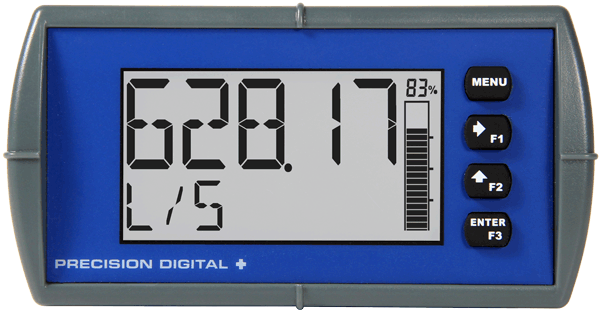
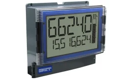
Display Features
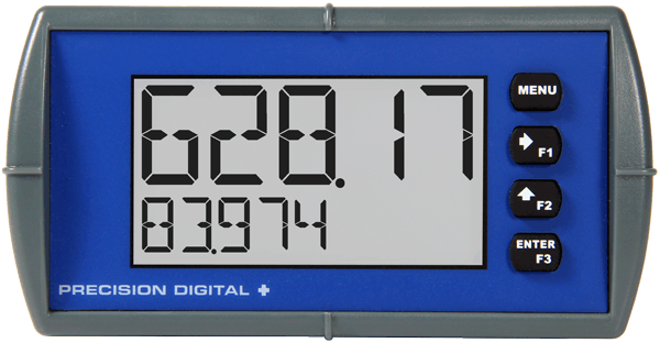
The Loop Leader’s display provides multiple ways to help users understand and keep track of their processes. The most obvious is the dual line which typically allows the user to display both flow rate and total at the same time. There is also a bargraph that includes a numeric value of the percentage the bargraph represents. Finally, to alert users to an alarm condition, the display can turn red and flash an alarm message.
Display Flow Rate & Total at Same Time
One of the key features of the Loop Leader Flow Rate/Totalizers is their ability to display flow rate and total at the same time. In addition, the meter can toggle between the rate and total and their corresponding units.

Toggle Flow Rate and Rate Units on Top,
Toggle Total Flow and Total Units on Bottom
Wide Variety of Display Capabilities
In addition to the most common setup of flow rate on the top line and flow total on the bottom line, these meters can be set up for a variety of display configurations.

Display Flow Rate and Toggle Between Units & Tag
The following table shows the items that can be displayed on the Top and Bottom lines:
Top Line Can Display:Off (Blank)Preset batch valueRateStopwatchRate and its units alternatingTimers OC and relaysTotalMinTotal and its units alternatingMaxTagMin & MaxUnits
Bottom Line Can Display:Off (Blank)Units for value on top lineTotal (with units or tag alternating)TagTotal, its units, and the rate and units alternatingPreset batch valueGrand total (with units or tag alternating)Tag and rate units alternatingGrand total, units, and rate units alternatingTag and total units alternatingRate (with units or tag alternating)Rate’s percentage of max scaleRate and the total’s units alternatingmA input valueRate or total unitsmA output value
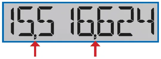
Commas on 8-Digit Totalizer for Easy Reading
It may seem like a simple thing, but adding commas to an eight-digit number makes it easier to read:

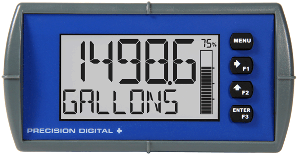
Bargraph Provides Quick Understanding
To help users get a quick understanding of where their process is at, certain Loop Leader skus are available with a 20-segment bargraph. This bargraph also includes a numeric value of the percentage the bargraph represents. The bargraph can be programmed to represent either the rate or total or it can be disabled.
Bargraph Based on Total
Alarms Indicated by Flashing Red Messages
When an alarm occurs, the Loop Leader’s display can be programmed to turn red and flash an alarm message along with the process variable and an alarm indicator (!). (Alarm indicator symbols are not available on bargraph skus) The Loop Leader’s flashing red alarm message can be activated even if no relay or open collector is connected.

Change Between Units without Needing to Re-Scale the Meter
It is possible to change the display units within the selected unit class without the need to re-scale the meter. When selecting a new unit from within the DISPLAY menu (e.g. changing from gallons (GAL) to liters (L)), the meter will automatically convert the display values to display the new unit. If entering a custom unit (CUSTM), a custom conversion factor will need to be entered.
Predefined and Custom Units
The meter has six available preprogrammed unit classes, volume, height, temperature, pressure, weight, and rate. When the desired unit class or unit of measure within a class is not available, a custom unit may be programmed by using the (CUSTOM) menu.
Max/Min Display
The max & min readings (peak & valley) reached by the process can be displayed either continuously or momentarily:
- Display momentarily by pressing the F1 key (default) or assigning to any of the other function keys or to the digital input in the User menu. Press Enter to lock/unlock max/min display.
- Display continuously by assigning either display line to max/min through the Display menu.
Any of the F1-F3 function keys (buttons) and the digital input can be programmed to reset the max & min readings.
Dual-Scale Display Feature
Users can use the Loop Leader’s dual-scale feature when they want to show the same input in two different scales. For instance, an application where the Loop Leader displays the input in gallons per minute and cubic feet per minute.

Rate in GPM on Top, Rate in CFM on Bottom
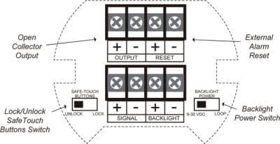
Outputs
Loop Leaders are available with two open collector outputs as standard and two solid state relays and 4-20 mA output as options. The open collector outputs and relays generally operate in the same manner, with the major exception being the open collectors are not available for batch control or sampling and the relays are not available with pulse features. The open collectors and relays can be controlled either automatically or manually. The alarm status (with flashing red message) will show on the display even with no output wired.
Two Open Collector Outputs
The Loop Leader is equipped with two NPN open collector outputs that may be set up for pulse outputs, alarms, timed pulses, stopwatch on/off, or disabled. Pulse outputs can be set to transmit the rate, total or grand total. Output 2 may be used to generate a quadrature output based on the other open collector output. An output test mode is also selectable to generate pulses at a constant programmable frequency. The open collectors are commonly used to generate a pulse for every user-defined amount of flow that has been generated. For instance, the Loop Leader can be programmed to generate a pulse for every 100 gallons of flow.
Two Optional Solid State Relays
The meter is optionally equipped with two solid state relays that may be set up for alarms, timer, stopwatch on/off, sample or batch control. The relays are rated at 250 VAC/DC @ 1 A for resistive loads and 75 VA @ 0.6 A, 250 VAC/DC max (Safe Area only) for inductive loads. Alarms are available based on the rate, total, grand total, or digital input.
Sampling Relay
A relay set to sample will trigger when the total or grand total value has incremented by a programmed amount. The relay can be programmed to stay on for a specified amount of time. For example: if a relay is set to sample the total with a COUNT of 1,000 and a TIME of 10 seconds, the relay will energize for 10 seconds each time the total increments by 1,000 (e.g. 1000, 2000, 3000).
Optional Isolated 4-20 mA Output
The isolated analog output signal can be configured to represent the rate, total or to retransmit the 4-20 mA signal input without the need to scale the output. While the output is nominally 4-20 mA, the signal will accurately accommodate under- and over-ranges from 1 to 23 mA. The output can be reverse scaled such that the meter’s high calibration value outputs 4 mA and the meter’s low calibration outputs 20 mA.
Resetting the Open Collectors and Relays
The open collectors and relays (alarms) may be programmed to reset in the following ways:
- Automatic (AUTO): Alarm will reset automatically once the alarm condition has cleared.
- Automatic/Manual (AUTO.MAN): Alarm will reset automatically once the alarm condition has cleared but can also be reset using the Enter button (or whichever function key is set to acknowledge) at any time.
- Latching (LATCH): Alarm must be reset manually and can be done so at any time. Press the Enter (ACK) button at any time to clear the alarm.
- Latching with Reset after Cleared (L-CLEAR): Alarm must be reset manually and can only be done so after the alarm condition has cleared. Press the Enter (ACK) button after the alarm condition has cleared to reset the alarm.
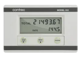
Totalizer Capabilities
Loop Leader flow rate/totalizers can be programmed for a wide variety of totalizer applications. They can display total, grand total, or non-resettable grand total; the rate can be displayed with a time base of seconds, minutes, hours or days. The user can program a totalizer conversion factor, a non-resettable grand total, password protection, and several total reset methods.
8-Digit Total & Grand Total Display, Up to 13 Digits Using Both Lines
The Loop Leader flow rate/totalizer can be programmed to show eight full digits of total on the bottom display or 13 digits of total using both the top and bottom displays. In both cases, the display can be programmed to include commas to make it easier to read the very large numbers; e.g. 44,987,356
In 13-digit mode, the bottom line shows the least significant digits and the top line shows the most significant digits. The meter is not capable of displaying commas on the top line, so this number is actually 1,211,230,379. The comas can be removed from bottom if desired. See sample on bottom, right.
Totalizer Conversion Factor & Multiplier
The user can enter a totalizer conversion factor that allows the meter to display total in different units than the rate. For instance, a customer could measure flow rate in gallons per minute and total in hundredths of acre-feet. A multiplier may be selected to automatically display the value in kGAL, MGAL, etc.
Totalizer Password Protection
The total and grand total can be password protected so they can be reset only by authorized personnel.
Non-Resettable Grand Total
The user can set up the grand total to be non-resettable by selecting YES for PERMLOCK in the Advanced – Grand Total – Reset menu. Once this is done, the grand total can never be reset.
Remote Total Reset
The total can be reset via an external contact closure on the digital input.
Front Panel Total Reset
The three front panel function keys can be programmed to reset the total and grand total. This makes it possible for the user to reset either the total or the grand total by pressing the appropriate function key. Of course, if the total or grand total is password protected, they will not reset when the function key is pressed unless the password is entered.
Low-Flow Cutoff
The user may program the meter for a low-flow cutoff such that the meter displays zero below this point, regardless of the input value.
Total Alarms
The Loop Leader’s two relays can be set up to alarm when the total reaches a user-defined set point. A variety of reset modes are available and the user can also program time delays and fail-safe operation.
Approvals
All versions of these instruments are CE marked. The hazardous area versions of these instruments are UL and C-UL Listed as intrinsically safe and nonincendive and ATEX and IECEx Certified for Intrinsic Safety in Hazardous Areas (Gas Atmospheres). These versions are also UL and C-UL Listed under the UL 61010-1 General Safety Standard.
One of the most useful aspects of the hazardous area approvals is that these instruments are approved by UL as nonincendive so they can be installed in Division 2 areas with no additional protective devices needed.