Introducing the Precision Digital PD6600, a versatile 1/8 DIN digital indicator designed to display any 4-20 mA signal with ease. This compact device can be installed almost anywhere, making it a convenient choice for various applications.
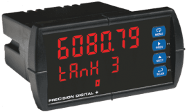
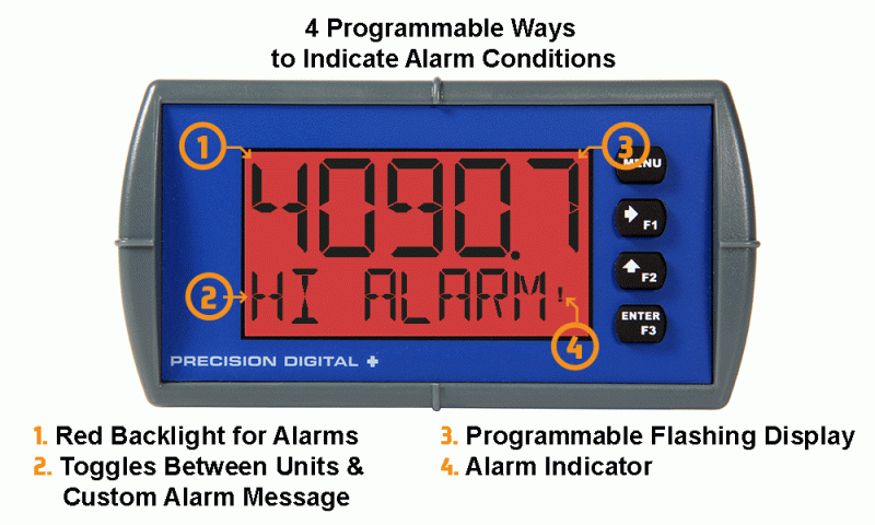
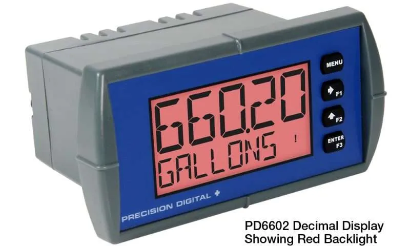
One of the standout features of the PD6600 is its dual-line display. The top line shows the process variable in a clear 5-digit alphanumeric format, while the bottom line can display units or tags in an 8-digit format. For example, you can view measurements in feet on the top line and gallons on the bottom line. The display uses 14-segment alphanumeric characters, ensuring that tags, units, and alarm messages are easy to read.
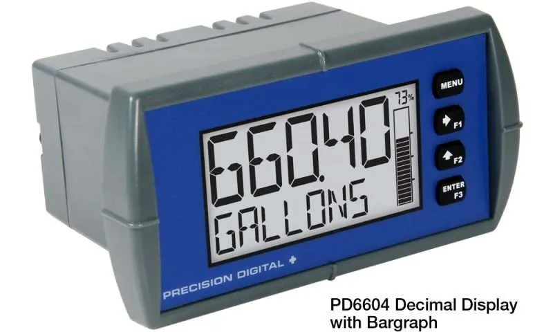
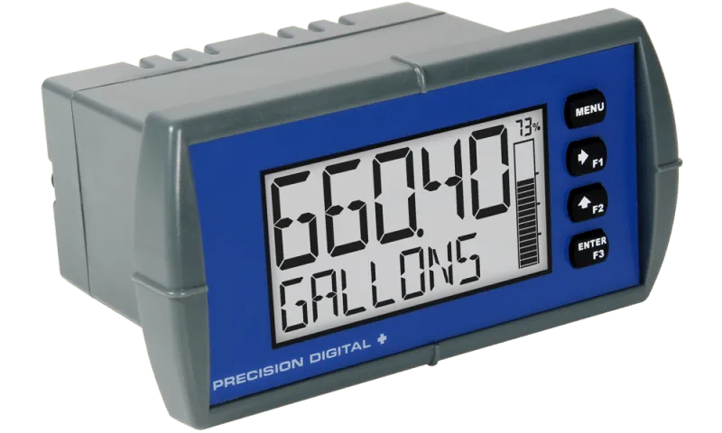
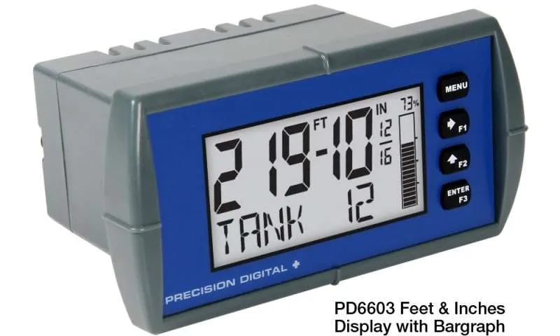
The PD6604 model enhances this experience with a 20-segment bar graph, which visually represents the percentage of the measured value alongside a numeric display. For those who prefer traditional measurements, there’s an option to display levels in feet and inches instead of decimals.
These loop-powered meters are incredibly flexible, as they draw power directly from the 4-20 mA loop, eliminating the need for an external power source. They only drop 1.5 V (or 4.7 V with backlight), ensuring minimal impact on the loop. The PD6600 is built to withstand various environments, featuring a NEMA 4X, IP65 rated front panel, and an operating temperature range of -40 to 167°F (-40 to 75°C) for safe area applications. The conformally coated PCBs and backlit LCD ensure readability in both bright sunlight and dim conditions. Additionally, intrinsically safe and non-incendive versions are available for use in hazardous locations.
Programming and setup are user-friendly with free PC-based software that connects via a micro USB cable. Alternatively, you can easily configure the meter using the four front panel buttons, three of which can serve as function keys. A standard digital input allows for remote alarm resets or triggering alarms.
All models come with two open collector outputs, and options for two solid-state relays and a 4-20 mA analog output. The open collector outputs are perfect for alarm indications or pulse outputs, while the relays can be programmed for alarm notifications, on/off control, or pump alternation.
- Brand: Precision Digital
- Material: Durable, conformally coated PCBs
- Size: 1/8 DIN
- Use Case: Ideal for displaying 4-20 mA signals in various environments
- Operating Temperature: -40 to 167°F (-40 to 75°C)
- Display: Dual-line with 5-digit and 8-digit alphanumeric characters
- Bar Graph: 20-segment with percentage display (PD6604 model)
- Power: Loop-powered, no external source needed
- Installation: NEMA 4X, IP65 rated, suitable for hazardous areas
SPECIFICATIONS
Except where noted all specifications apply to operation at +25°C.
Input
Input: 4-20 mA
Accuracy: ±0.02% of span ±1 count, Square root and programmable exponent: 10-100% FS
Voltage Drop: Without Backlight: 1.5 V maximum,
With backlight: 4.7 V maximum
Equivalent Resistance: With backlight off: 75 Ω @ 20 mA
With backlight on: 225 Ω @ 20 mA
Input Overload: Over current protection to 1 A maximum
Temperature Drift: 25 PPM/°C from -40 to 75°C ambient
Function: PV1: Linear, square root, or programmable exponent PV2: Linear or Round Horizontal Tank
Low-Flow Cutoff: 0.0 to 999,999.9
HART Transparency: Analog input will not interfere with existing HART communications on the wired 4-20 mA signal
Display
Display: Dual-line LCD with backlight. Both lines are 14-segment alphanumeric. Top: 0.7″ (17.8 mm), Bottom: 0.4″ (10.2 mm). The display may be programmed to turn red and flash a user-defined message on an alarm condition.
Backlight: Powered by 4-20 mA loop. Intensity varies with signal level
PD6602 & PD6606:
Top line: 5 digits (-9999 to 99999) or 5 characters (all capital & most lower case letters)
Bottom line: 8 digits (-9,999,999 to 99,999,999; separated by commas) or 8 characters (all capital & most lower case letters)
Bargraph: None
PD6603 & PD6607:
Top line: -99FT 11IN 15/16 to 999FT 11IN 15/16
Bottom line: 8 digits (-9,999,999 to 99,999,999; separated by commas) or 8 characters (all capital & most lower case letters)
Bargraph: 20 segments, numeric percent indication at top
PD6604 & PD6608:
Top line: 5 digits (-9999 to 99999) or 5 characters (all capital & most lower case letters)
Bottom line: 8 digits (-9,999,999 to 99,999,999; separated by commas) or 8 characters (all capital & most lower case letters)
Bargraph: 20 segments, numeric percent indication at top
Decimal Point & Commas:
Topline: Up to four decimal places
Bottom line: Up to seven decimal places and commas to indicate 1000s (ie 88,987,628)
Dual-Scale Feature: The input can be displayed in different scales on the top and bottom lines. For instance, the top line could display the input in height and the bottom line could display that same input in volume.
Alarm Indication: Red backlight, flashing display, alarm symbol (!). Symbols are not available on bargraph models.
Alarm Message: On or Off; user programmable, 8 characters maximum. Displayed every 10 seconds for 1 second on bottom line.
Display Update Rate: Ambient > -10°C: 1 update/second
Ambient -20 C: 1 update/2 seconds
From -20°C to -40°C the update rate slows down 1 second for every -2°C (e.g. at -24°C, 1 update/4 seconds).
Overrange: Top: 99999; Bottom: 99,999,999 (flashing)
Underrange: Top: -9999; Bottom: -9,999,999 (flashing)
General
Environmental: Operating temperature range:
-40 to 75°C for safe area products
-40 to 70°C for hazardous area products
Storage temperature range: -40 to 85°C
Relative humidity: 0 to 90% non-condensing. Printed circuit boards are conformally coated.
Programming Method: Front panel & Free PC-based USB programming software
Enclosure & Materials: Enclosure: 1/8 DIN, IP65, NEMA 4X front panel, high impact plastic, NORYL® polyphenylene ether & polystyrene blend (PPE PS) resin, UL 94V-0, Color: gray, Gasket: silicone rubber, Faceplate: LEXAN® polycarbonate (PC) film, Buttons: silicone rubber
Noise Filter: Averages the input signal over a period of time between 1 and 16 seconds to dampen the effects of a noisy signal that causes a jumpy display.
Recalibration: Recalibration is recommended at least every 12 months.
Max/Min Display: Max/min readings reached by the process are stored until reset by the user or until power to the meter is turned off.
Tare: Zeros out display
Password: Programmable password restricts modification of programmed settings.
Non-Volatile Memory: All programmed settings are stored in nonvolatile memory for a minimum of ten years if power is lost.
Normal Mode Rejection: 64 dB at 50/60 Hz
Connections: Removable screw terminals accept 12 to 22 AWG wire.
DI Digital Input Contacts: 2.1 VDC on contact. Connect normally open contacts across DI+ and DI
DI Digital Input Logic Levels: Logic High: 2.4 to 30 VDC (max)
Logic Low: 0 to 0.9 VDC
Tightening Torque: Screw terminal connectors: 4.5 lb-in (0.5 Nm)
Mounting screws: 8.0 lb-in max. (0.9 Nm)
Overall Dimensions: 4.68″x 2.45″x 3.79″ (119 mm x 62 mm x 96 mm) (W x H x D)
Weight: 8.7 oz (247g) with option board
Warranty: 3 years parts and labor
Common Open Collector & Relay (Alarm) Specifications
High or Low Alarm: User programmable for high or low alarm
Alarm Deadband: 0-100% FS, user programmable
On & Off Time Delay: 0 to 9,999 seconds
Fail-Safe Operation: Independent for each open collector and relay
Alarm Operation: Automatic, Automatic with manual override, Latching (manual reset anytime), Latching with a reset after cleared (manual reset only after the alarm has cleared)
Alarm Indication: Red backlight, flashing display, alarm symbol (!); (symbols not available on bargraph skus)
Alarm Message: On or Off; User programmable, 8 characters maximum. Displayed every 10 seconds for 1 second on the bottom line
Alarm Acknowledge: Front panel ACK button or external digital input resets output and screen indication
Auto Initialization: When power is applied to the meter, open collectors and relays will reflect the state of the input to the meter
Timer Output: One-shot or Continuous
Off Time Delay: 1 sec to 99:59:59 (hrs:min:sec)
On Time: 1 sec to 99:59:59 (hrs:min:sec)
Stopwatch: Output turns on when started and off when stopped
Open Collector Outputs
Rating: Two NPN, Isolated open collector, 30 VDC @ 150 mA max
Output Assignment: Pulse, Alarm, Timer, Stopwatch on/off, or Disable
Pulse Output Source: PV (PV1, PV2) or Test Frequency
Pulse Output Factor: 0.000001 to 999,999.9
Pulse Width: 0.5 ms @ 1 kHz; 500 ms @ 1 Hz; 50% duty cycle
Pulse Output Frequency: 1,000 Hz maximum
Quadrature Pulse Output: Available for Output 2 (90° behind Output 1)
Alarm Output Source: Assign to PV (PV1, PV2) or Digital Input
Solid State Relays
Rating: Resistive Load: 250 VAC/DC @ 1 A
Inductive Load: 75 VA @ 0.6 A, 250 VAC/DC max (Safe Area only)
Noise Suppression: Metal oxide varistors across outputs
Relay Assignment: Pump Alternation, Alarm, Timer, Stopwatch on/off, or Disable
Alarm Output Source: Assign to PV (PV1, PV2) or Digital Input
Pump Alternation: Relays will alternate with each pump cycle and alternation can be based on elapsed time. Pump alternation time can be programed for: 0 to 999:59 (hrs:min)
Relay (Pump) Runtime: Meter will keep track of how long each relay (pump) has operated and display this information
Relay (Pump) Cycles: Meter will keep track of how many times the relays (pumps) have cycled and display this information
4-20 mA Transmitter Output
Accuracy: ±0.05% FS ±0.001mA
Output Source: PV1, PV2, re-transmit; reverse scaling allowed
Scaling Range: 1.00 to 23.0 mA
Disable: High impedance state, less than 1 mA
Calibration: Factory calibrated 4.00 to 20.00 mA
Underrange: 1.0 mA, 3.5 mA, or 3.8 mA (If input < 3.5 mA), or Off; user selectable
Overrange: 20.5 mA, 20.8 mA, or 23.0 mA (If input > 20.5 mA), or Off; user selectable
Isolation: 500 V input-to-output
Temperature Drift: 0.5 μA/°C max from -40 to 75°C ambient
External Loop Power Supply: 7.0 VDC to 30.0 VDC maximum
Output Loop Resistance: 10-750 Ω @ 24 VDC; 100-1100 Ω @ 30 VDC
Applications
Signal Input Conditioning
Non-linear input signals (i.e. weirs & flumes, differential pressure, etc.) can be linearized with the ProVu’s simple to use built-in signal input conditioners, such as square-root extractor, exponential linearizer, horizontal round tank linearizer, or the ProVu’s powerful general-purpose 32-point linearizer.
Weir Flow Calculated Using Exponential Math Function

Round Horizontal Tank Math Function
Multi-Pump Alternation
For pump control applications where 2 or more similar pumps are used to control the level of a tank or a well, it is desirable to have the pumps operate alternately; this prevents excessive wear and overheating of one pump over the lack of use of the others. The ProVu can accommodate up to 8 pumps. In the example below, a pair of relays have been set up to alternate every time an on/off pump cycle is completed. Another pair of relays is used for low and high alarms.
Connections
Free Meterview XL PC-Based Programming Software

The main screen displays an image of the connected meter and includes various information about this meter, such as model number, readings, and status.
Free, PC-based, MeterView XL software that connects to the meter via a micro USB cable is available for programming and setup of the meters. This software greatly simplifies the programming process and also allows the user to save configuration files for later use. The meter will also be powered by a USB connection so no additional power is needed during programming.
- Free
- Easiest Way to Program Your Loop Leader
- Convenient USB Connection
- Meter Powered by USB Connection During Programming
- Save & Print Configuration Files without Meter Connected
- Micro USB Cable Provided
Mounting Dimensions

Notes:
- Panel cutout required: 1.772″ x 3.622″ (45mm x 92mm)
- Panel thickness: 0.040 – 0.250″ (1.0mm – 6.4mm)
- Mounting brackets lock in place for easy mounting
- Clearance: Allow 6″ (152 mm) behind the panel
Applications
Pump Control
Loop Leaders, when ordered with the two solid-state relays, have several features that make them ideal for simple duplex pump control. The relays can be programmed to alternate the pumps based on level and runtime thus ensuring even wear on both pumps. If the level remains constant (within on/off points), alternation is based on runtime. If the level cycles the on/off points, alternation is based on level and runtime. If the run time is set to 0, alternation is based on level. The meter also keeps track of runtime for both pumps and the number of times they have cycled.
In addition to the two solid-state relays for controlling pumps, the Loop Leaders two open collectors could be used to indicate high or low-level alarm conditions.
Pump Alternation
The Loop Leader can be used as a pump controller to alternate two pumps and provide high and low-level alarm indications. The pumps can be programmed to alternate on the level and run time and the meter can display the pump run times and the number of times they have cycled. The PD6606–L2N can be used as an intrinsically safe pump controller.

Signal Input Conditioning
The PD6600 Loop Leader process meter allows you to select the signal input conditioner applied to the input: linear, square root, programmable exponent, or round horizontal tank volume calculation.
The programmable exponent function is used to linearize the level signal in open channel flow applications using weirs and flumes and display flow rate in engineering units.
The square root function can be used to linearize the signal from a differential pressure transmitter and display flow rate in engineering units.
The round horizontal tank linearization function automatically calculates the volume in a round horizontal tank with flat ends.
Digital Input
A digital input comes standard on the Loop Leader PD6600 Series. This allows the user to program an external button to activate certain functions immediately like alarm acknowledgment, display minimum/maximum values, tare the display, reset a value, and many more. This allows the Loop Leader to be greatly customized for use in specialized applications. See the PD6600 series manuals for all digital input functions.
Timer Function
Application Timers are used in everyday life; one of the most common examples is the microwave oven. Industrial timers are used in process control applications where certain events or actions need to be controlled by time. Examples include automatic and batch control applications, where the relay needs to be energized for a specific length of time.
The timer function is available on the open collector and relay outputs; which means that you can have up to four timers per meter. The start and stop actions can be triggered from the setup menu or by the function keys and digital input. The meter can be setup to display the off/on timer count down.
There are two modes of operation:
- Continuous Timer (Interval)
At the start of the timer, the output is off and turns on after the Off Delay elapses. The output remains on for the duration of the On Time. The cycle repeats until the user stops the timer either from the menu or a function key. - One-Shot Timer
At the start of the timer, the output is off and turns on after the Off Delay elapses. The output remains on for the duration of the On Time. The timer stops and the cycle does not repeat.

- A sensor detects the bottle is in place and triggers the digital input to start the timer
- The timer output controls the filling pump
- The On Time is set according to the time needed to fill the bottle
Connections
Connectors Labeling
The connectors’ label, affixed to the meter, shows the location of all connectors available with requested configuration.

Current Loop (4-20 mA) Connections
The following figures show a 4-20 mA current loop connected to the meter. The first figure shows the connection with the backlight disabled and the second shows the connection with the backlight enabled. The meter is powered by the 4-20 mA current loop.

Digital Input Connection
A digital input is standard on the meter. This digital input is connected with a normally open contact across DI+ and DI-, or with an active low signal applied to DI+.

4-20 mA Output Connections
Connections for the 4-20 mA transmitter output are made to the connector terminals labeled MA OUT. The 4-20 mA output must be powered from an external power supply.

Relay Connections
Relay connections are made to two four-terminal connectors. Each relay’s C terminal is common only to the normally open (NO) contact of the corresponding relay.

Open Collector Outputs
Open collector output 1 and 2 connections are made to terminals labeled O1+ and O1-, and O2+ and O2-. Connect the alarm or pulse input device as shown below.
