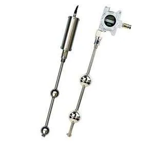
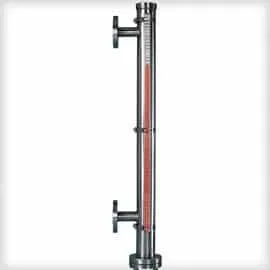
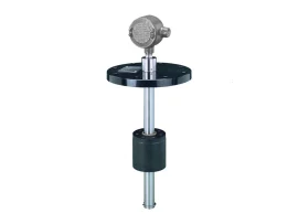
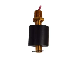
| Fine-Tek EGX Magnetostrictive Level Transmitter |
| ● GENERAL DESCRIPTION |
| Type | Magnetostrictive Level Transmitter |
| Measuring Principle | A magnetostrictive wire is sealed inside a stem/rod; a permanent magnet is sealed inside a float that moves up/down the stem. Current pulsed along the wire creates an axial magnetic field; where it intersects the float’s magnetic field, a torsional (twist) pulse is generated. The transmitter measures liquid level by timing the elapsed interval between the pulse launch and the returned torsional wave, then converts elapsed time to distance/level. |
| Model Series | EG374 (anti-corrosion, 2-wire), EG371 (single/dual float, 2-wire), EG37A (explosion-proof high-temp, 2-wire), EG36 (display type, explosion-proof, 2-wire), EG50 (4-wire), EG60 (2-wire or 4-wire) |
| Output | Analog 4~20mA / 20~4mA (loop powered) and/or digital RS485 (ModBus) or HART 7.3, depending on model; EG60 4-wire also offers 0~10V/10~0V/0~5V/5~0V voltage outputs |
| Application | Continuous liquid level measurement; liquefied natural gas, crude oil/petroleum/diesel, chemical processing, pharmaceuticals, food and beverage, water/wastewater treatment, power plants, marine/shipbuilding, and machine tooling/alignment positioning. Dual-float versions also provide oil/water interface indication. |
| |
| ● MATERIALS |
| Housing Material (EG374/EG371/EG37A/EG50/EG60) | SUS304 (SUS316 optional) |
| Housing Material (EG36) | Aluminum |
| Wetted Material (EG374) | PP |
| Wetted Material (EG371/EG37A/EG36/EG50/EG60) | SUS304 (SUS316 optional on EG50) |
| Probe Material Options (order code) | SUS304, SUS316, SUS316L, or PP coating |
| Float Material Options | SUS304/316, SUS316/316L, PP in Grey (coated), PP in Black (coated), or NBR in Black |
| |
| ● ELECTRICAL / PERFORMANCE RATINGS |
| Parameter | EG374
(Anti-Corrosion) | EG371
(Single/Dual Float) | EG37A
(Ex-proof High Temp) | EG36
(Display) | EG50
(4-Wire) | EG60
(2-Wire) | EG60
(4-Wire) | | Application | 2-wire loop power, acid/alkali corrosion liquids | 2-wire loop power, single/dual level & interface measurement | 2-wire loop power, explosion-proof, hazardous environments | 2-wire loop power, explosion-proof with display, hazardous environments | Four wire output | 2-wire loop power, HART-compliant | Four wire output | | Measuring Range | 50~2000mm | 50~5500mm | 50~5500mm | 50~5500mm | 50~1000mm | 50~5500mm | 50~2500mm | | Non-Linearity / Linearity | ±0.05% F.S. or ±1.0mm (whichever greater) | ±0.05% F.S. or ±1.0mm (whichever greater) | ±0.05% F.S. or ±1.0mm (whichever greater) | 50~4000mm: ±1mm; 4000~5500mm: ±0.025% F.S. | >500mm range: ±0.1% F.S.; ≤500mm range: ±500µm | 50~2000mm: 1mm; 2001~5500mm: 0.05% F.S. | Selectable per range/output: (50~500mm) 0.1/0.2/0.5mm; (500~2500mm) 0.02%/0.05%/0.1% F.S. | | Repeatability | ±0.004% F.S. | ±0.004% F.S. | ±0.004% F.S. | ±0.004% F.S. | ±0.005% F.S. | ±0.002% F.S. | ±0.002% F.S. | | Temp. Coefficient | ±100 ppm/°C | ±100 ppm/°C | ±150 ppm/°C | ±100 ppm/°C | ±100 ppm/°C | ±100 ppm/°C | ±100 ppm/°C | | Operation Pressure | 5 BAR (Max.) | 30 BAR (Max.) | 30 BAR (Max.) | 30 BAR (Max.) | 30 BAR (Max.) | 30 BAR (Max.) | 30 BAR (Max.) | | Ambient Temp. | -40°C ~ 85°C | -40°C ~ 85°C | -40°C ~ 85°C | -40°C ~ 85°C | -40°C ~ 85°C | -40°C ~ 85°C | -40°C ~ 85°C | | Operation Temp. | -20°C ~ 80°C | -40°C ~ 125°C | -40°C ~ 195°C | -40°C ~ 125°C | -40°C ~ 125°C | -40°C ~ 125°C (Std.); -40°C ~ 195°C (High-temp model) | -40°C ~ 125°C (Std.); -40°C ~ 195°C (High-temp model) | | Temp. Accuracy | ±1°C | ±1°C | ±1°C | ±1°C | ±0.5°C | ±0.5°C | ±0.5°C | | Output | 4~20mA / 2 Wire | 4~20mA / 2 Wire | 4~20mA / 2 Wire | 4~20mA / 2 Wire | 4~20mA / 20~4mA | 4~20mA / 20~4mA | 0~10V, 10~0V, 0~5V, 5~0V, 4~20mA, 20~4mA | | Max Load | (VS-18)÷0.02 Ω, VS=Supply voltage | (VS-18)÷0.02 Ω | (VS-18)÷0.02 Ω | (VS-16)÷0.02 Ω | (VS-18)÷0.02 Ω | (VS-18)÷0.02 Ω | 500Ω | | Digital Output | RS485 / HART 7.3 (option) | RS485 / HART 7.3 (option) | RS485 / HART 7.3 (option) | RS485 / HART 7.3 (option) | RS485 (option) | RS485, HART (option) | RS485 (option) | | Power Supply | 12~30V(4-wire), 18~30V(2-wire), 18~28V(Ex-proof) | 12~30V(4-wire), 18~30V(2-wire), 18~28V(Ex-proof) | 12~30V(4-wire), 18~30V(2-wire), 18~28V(Ex-proof) | 12~30V(4-wire), 16~30V(2-wire), 16~28V(Ex-proof) | 18~30V | 18~30V | 18~30V | | Housing Material | SUS304 (SUS316 option) | SUS304 (SUS316 option) | SUS304 (SUS316 option) | Aluminum | SUS304 (SUS316 option) | SUS304 (SUS316 option) | SUS304 (SUS316 option) | | Connection | 3/4″PT | 1/2″PT | 1/2″PT | 1/2″PT | M18x1.5 | 1/2″PT | 1/2″PT | | Wetted Material | PP | SUS304 | SUS304 | SUS304 | SUS304 (SUS316 option) | SUS304 | SUS304 | | Enclosure | IP67 (Enclosure) / IP69K (Probe) – all models |
Note: “Max Load” is expressed in ohms (Ω) – the source symbol for ohm rendered ambiguously in text extraction but was confirmed as Ω via the rendered PDF page image, not “W” (Watts). |
| |
| ● FLOAT SPECIFICATIONS |
| Float Code | Dimensions (⌀A x B x ⌀C mm) | Min. S.G. | Max. Pressure (kg/cm²) | Material | Stem Size (⌀) | | S5 | 75x73x20.5 | >0.7 | 30 | SUS304/316 | 16mm | | S4 | 52x52x15 | >0.75 | 30 | SUS316 | 12.7mm | | SD | 52x52x15 | >0.9 | 30 | SUS316 | 12.7mm | | SE | 75x73x20.5 | >0.9 | 20 | SUS304/316 | 16mm | | A1 | 32x69x10.9 | >0.75 | 10 | SUS316/316L | 8mm | | AA | 32x69x10.9 | >0.9 | 10 | SUS316/316L | 8mm | | S3 | 45x55x15 | >0.7 | 12 | SUS316 | 12.7mm | | SC | 45x55x15 | >0.9 | 12 | SUS316 | 12.7mm | | F3 | 45x45x20 | >0.65 | 5 | PP in Grey | 18mm (coating) | | FC | 45x45x20 | >0.9 | 5 | PP in Grey | 18mm (coating) | | P3 | 48x45x18.5 | >0.6 | 5 | PP in Black | 17.2mm (coating) | | PC | 48x45x18.5 | >0.9 | 5 | PP in Black | 17.2mm (coating) | | NB | 48x46x15.6 | >0.5 | 30 | NBR in Black | 12.7mm | | ND | 48x46x15.6 | >0.9 | 30 | NBR in Black | 12.7mm | | NC | 48x46x20 | >0.5 | 30 | NBR in Black | 16mm | | NE | 48x46x20 | >0.9 | 30 | NBR in Black | 16mm |
S.G.(E) = specific gravity threshold; probe diameter must be smaller than the float’s hole diameter. “Min. S.G.” values are minimum liquid specific gravity for the float to function. |
| |
| ● DIMENSIONS (mm) |
| EG374 / EG371 Body Height | 130mm; connection block 34mm (EG374) / 30mm (EG371); probe ⌀17.2mm (EG374, PP coated) or ⌀16mm (EG371); float assembly ⌀75 x 73mm (EG371); M12 connector on top. Probe length “L” is the ordered stem length (variable, per length code). |
| EG37A Body Height | 130mm block, 15mm/120mm threaded section, probe ⌀16mm, float assembly ⌀75 x 73mm, M12 connector |
| EG36 Junction Box | 167mm (W) x 208mm (H) explosion-proof junction box, probe stem length “L” variable, float assembly ⌀75 x 73mm |
| EG50 Body Height | 60.5mm block, 14mm connection collar; upper blank distance 51mm (dual-float interface version) or 15mm (single float); lower blank distance 15mm; M12 connector |
| EG60 Body Height | 80mm block, 30mm/20mm connection collar; probe ⌀17.2mm (2-wire) with float ⌀75 x 73mm; upper blank distance 15mm; ordered length = L; M12 connector |
| Housing Conduit Options (⌀50mm block diameter, all) | EG37 Explosion-proof (2 wire): Top conduit 130mm / Side conduit 134mm. EG50 Four wire: Top conduit 60.5mm / Side conduit 60.5mm. EG60 Two/Four wire: Top conduit 80mm / Side conduit 80mm. Standard cable length is 2m. |
| Stem Length Conversion (Ordered vs. Actual Measurable) | Stem ⌀12.7mm, cable ≤2m: Actual measurable length (X) = Ordered length (L) − 52mm − 15mm
Stem ⌀16mm, cable >2m: Actual measurable length (X) = Ordered length (L) − 73mm − 15mm
Stem ⌀12.7mm, cable ≤2m: Ordered length (L) = Actual measurable length (X) + 52mm − 15mm
Stem ⌀16mm, cable >2m: Ordered length (L) = Actual measurable length (X) + 73mm − 15mm
Stem ⌀12.7mm with PP coating to ⌀17.2mm: blanking zone at end = 25mm (48mm collar / 45mm coated section) |
| |
| ● WIRING / CONNECTIONS |
| EG37 / EG60 (2-Wire), M12 Connector – Single/Double Float + RS485 (Loop Power 24Vdc ±10%) |
| Pin | Wire Color | Function | | 1 | Brown | Loop Power (+) (CH1) | | 3 | Blue | Loop Power (−) (CH1) | | 2 | Green | RS485 (+) | | 4 | Black | RS485 (−) |
|
| EG37 / EG60 (2-Wire) – Single/Double Float + HART |
| Pin 1 (Brown): Loop Power 4~20mA. Pin 3 (Blue) and Pin 2 (Green): connect to DC power supply, 18~30V. Pin 4 (Black): HART loop resistor 250~500Ω, tapped to a HART modem which connects to a PC via RS232. |
| EG36 – Terminal Block |
<| Terminal | Label | Function | | 1 | DATA+ | D+: RS485 (+) | | 2 | DATA- | D−: RS485 (−) |
|