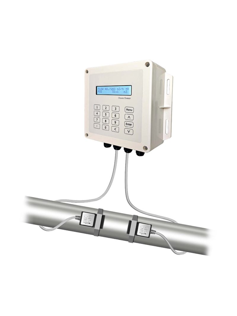
The Celectric FUF8300 is a clamp-on ultrasonic flow meter that works on the transit-time (time-difference) measurement principle. A pair of transducers mounted on the outside of the pipe sends ultrasonic signals through the flowing liquid. A signal travelling downstream moves faster and a signal travelling upstream moves slower, so the two cover the same path in different times.
The difference between the upstream and downstream transit time (travel time, or time of flight) is proportional to the flow velocity, and the FUF8300 uses it to calculate the flow rate:
V = K × (Tup − Tdown) / (Tup + Tdown)
Key Features
- Protection: Transmitter IP65, transducer IP68.
- Bi-directional Measurement: Bi-directional flow measurement with cumulative flow.
- Proven Reliability: 50,000 hours test without trouble.
- Flow Statistics: Flow statistics by period.
- Durable Keypad: Key life of more than 200,000 presses.
- Outputs and Communication: RS485 communication interface, 4–20mA current signal, pulse output, Modbus protocol.
- SLSI Technology: Fewer hardware components, low voltage broadband pulse transmission, low power consumption, high reliability, anti-jamming and outstanding applicability.
Applications
- Water Treatment & Wastewater Treatment
- Construction and HVAC Systems
- Chemical Industry
- Food & Beverage Industry
- Agriculture and Irrigation
- Oil & Gas Production
- Urban Drainage Systems
- Rivers, Canals, and Reservoirs
- Environmental Monitoring
Technical Specifications
| Feature | Specification |
|---|---|
| Performance Specifications | |
| Flow Range | 0.03 to 16 ft/s (0.01 to 5.0 m/s) |
| Accuracy | ±1.0% of measured value |
| Pipe Size | Clamp-on: 1″ to 48″ (25mm to 1200mm) |
| Fluid | Water |
| Function Specifications | |
| Outputs | Analog output 4–20mA, max load 750Ω; OCT pulse output 0–5000Hz |
| Communication Interface | RS485 Modbus |
| Power Supply | 10 to 36VDC / 1A |
| Keypad | 16 (4×4) keys with tactile action |
| Display | 20×2 lattice alphanumeric, backlit LCD |
| Temperature | Transmitter: -10°C to +50°C (14°F to 122°F); Transducer: 0°C to 80°C (32°F to 176°F) |
| Humidity | Up to 99% RH, non-condensing |
| Physical Specifications | |
| Transmitter | PC/ABS, IP65 |
| Transducer | Encapsulated design, IP68 |
| Transducer Cable | Standard cable length: 5m |
| Weight | Transmitter: approximately 0.7kg; Transducer: approximately 0.4kg |
Structure
The FUF8300 consists of a transmitter and a pair of clamp-on transducers:
- Transmitter: Housing with display and keypad panel.
- Transducers: Strapped onto the outside of the pipe and connected to the transmitter by cable.
Installation
Straight Pipe Requirements
Install the transducers on a straight section of pipe. D is the pipe diameter and L is the straight length required.
| Fitting | Straight length of upstream piping | Straight length of downstream piping |
|---|---|---|
| 90° Bend | L ≥ 10D | L ≥ 5D |
| Tee | L ≥ 50D | L ≥ 10D |
| Diffuser | L ≥ 30D | L ≥ 5D |
| Reducer | L ≥ 10D | L ≥ 5D |
| Valve | L ≥ 30D (flow controlled upstream) | L ≥ 10D (flow controlled downstream) |
| Pump | L ≥ 50D (after the pump, stop valve and check valve) | – |
- Ensure that the pipe surface temperature at the measuring point is within the transducer temperature limits.
- Consider the inside condition of the pipe carefully. If possible, select a section of pipe where the inside is free of excessive corrosion or scaling.
Transducer Mounting Method
Three transducer mounting methods are available for the FUF8300: V method, Z method and N method.
The V method is primarily used on small diameter pipes (DN100 to 300mm, 4″ to 12″). The Z method is used in applications where the V method cannot work due to poor signal or no signal detected. In addition, the Z method generally works better on larger diameter pipes (over DN300mm, 12″) or cast iron pipes. The N method is an uncommonly used method. It is used on smaller diameter pipes (below DN50mm, 2″).
V Method
The V method is considered the standard method. It usually gives a more accurate reading and is used on pipe diameters ranging from 25mm to 400mm (1″ to 16″) approximately. It is convenient to use, but still requires proper installation of the transducers: contact on the pipe at the pipe’s centerline and equal spacing on either side of the centerline.
Z Method
The signal transmitted in a Z method installation has less attenuation than a signal transmitted with the V method. This helps when the pipes are too large, there are some suspended solids in the fluid, or the scaling and liner are too thick, because the Z method uses a directly transmitted (rather than reflected) signal which traverses the liquid only once.
The Z method is able to measure on pipe diameters ranging from 100mm to 800mm (4″ to 32″) approximately. The Z method is therefore recommended for pipe diameters over 300mm (12″).
N Method (not commonly used)
With the N method, the sound waves traverse the fluid three times and bounce twice off the pipe walls. It is suitable for small pipe diameter measurement. The measurement accuracy can be improved by extending the transit distance with the N method.