
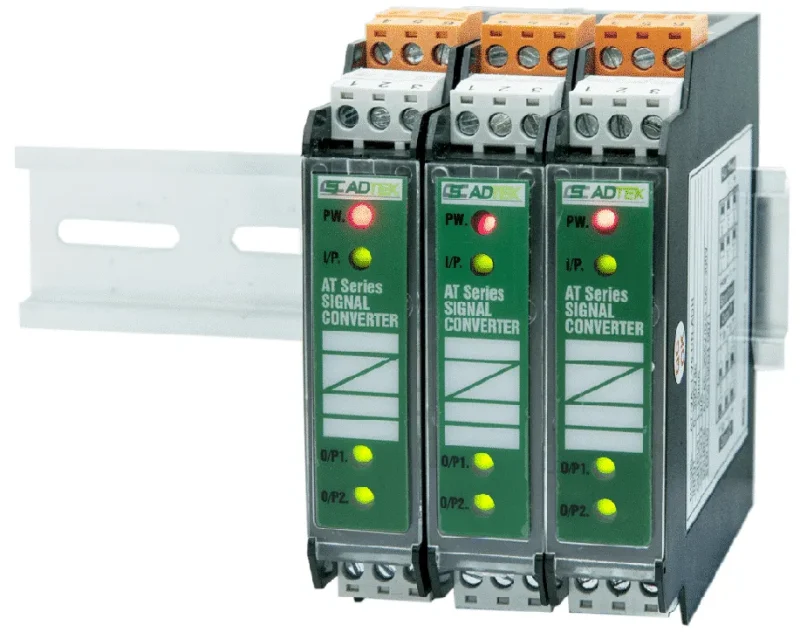
AT-PR: DC Current 0/4~20mA, Voltage 0/1~5/10V (switchable)
Output Loop: Dual Output
Input : 4 – 20mA
Output 1: 4 – 20mA
Output 2: 4 – 20mA
Aux Power: 85 – 264VAC
Adtek AT Series Signal Converter
Adtek AT-PR2-A5-DD-ADH
| Adtek A7-SG Automatic Control Weighing Indicator Technical Specifications | |
|---|---|
| ● GENERAL | |
| Description | High precision automatic/dispatch controller specially designed as an engineering control batch controlling meter, applied for automatic control of batch measuring, dispatching and mixing. Equipped with different batching procedures, the device can be utilized widely for batching control systems — single or multiple materials for automatic portioning, mixing, discharging, batching, etc. — with easy integration to PLC, HMI or a computer. |
| Key Features | Industrial grade design for tough industrial environments; noise and interference protection efficiently blocking power, microwave and radio interference; dual display panel showing weight and several setting values simultaneously; digital intelligent filtering functionality stabilizes usage in unstable environments; formula, settings, logic output, function setting and weight calibration can be fine-tuned or calibrated through buttons or RS485; equipped with RS-485 serial interface for remote display, computer, PLC and HMI (supports Modbus RTU and ASCII); standard edition equipped with 8 input control connectors and 8 relay output connectors, customizable by user or defined through RS-485 communication; can save 0~30 codes, each code output-controlling weight settings including target weight (Final), first stage of fast feeding, mass supply, mass dispatch (SP1), second stage of middle feeding, middle supply, middle dispatch (SP2), drop weight (SP3), around zero point weight (Z.Band), high weight limit (HI) and low weight limit (LO). |
| Typical Applications | Weighing machine; weighing check with Hi/OK/Lo; filling machine; mixture machine; force testing equipment. |
| ● INPUT | |||
| Input Range | Input Impedance | Display Range | Resolution |
| -1 mV ~ 37 mV | ≥ 69 KΩ | -199999 ~ 999999 | 0.00001 |
| ● INPUT — ADDITIONAL PARAMETERS | |
| Input Sensitivity | 0.12 µV/D (minimum). |
| Conversion Rate | Approximately 100 times/sec. (max.) |
| Load Cell Excitation Voltage | 5 Vdc ±5%, 120 mA (up to eight 350Ω load cells can be connected). |
| Internal Resolution | 24 bits. |
| Calibration | 2-point or multi-points calibration applicable; various calibration points can be adjusted independently. |
| ● DISPLAY & FUNCTIONS | |
| Main Display | 7 digits, bright red 7-segment LED display, character height 0.8 (in.). |
| Indication Icons | 12 red display 3 LED. |
| Unit Indication | 3 red 3 LED. |
| Display Update Rate | 50 times/sec. |
| Display Capacity | -199999 to 999999. |
| Decimal Point | 0 / 0.0 / 0.00 / 0.000 / 0.0000 / 0.00000. |
| Minimum Division | 1 / 2 / 5 / 10 / 20 / 50. |
| Memory | Calibration parameters and function settings saved in EEPROM. |
| Zero Track Time / Range | Time: 00.0~10.0 sec. Range: 00.0~10.0 D. |
| Motion Detect Time / Range | Time: 00.0~10.0 sec. Range: 00.0~10.0 D. |
| Unit | Programmable Kg / t / lb. |
| ● CONTROL FUNCTIONS | |
| Control Relay | 8 sets relay, FORM-A, 1A/230Vac, 2A/115Vac. |
| Relay Action Mode | Hi / OK / Lo / Zero Band / SP1 / SP2 / SP3 / FINAL / UART / OL / UN-LD / RING. |
| Relay Contact Form | Can be set ON or OFF. |
| ● ANALOGUE OUTPUT | |
| Accuracy | ≤ ±0.1% of F.S.; 16-bit DA converter. |
| Ripple | ≤ ±0.1% of F.S. |
| Response Time | ≤ 100 mS (10~90% of output). |
| Isolation | 1 MΩ between input and output. |
| Output Range | Voltage: 0~5V / 0~10V. Current: 4~20mA. |
| Output Capability | Voltage 0~10V: ≥ 2000Ω. Current 4~20mA: ≤ 300Ω. |
| Functions | DA compare source; weight value phase; DA output logic; lower point of weight value (0~999999); higher point of weight value (0~999999). |
| Digital Fine Adjust | Amend lower point digital output: 0~65535. Amend higher point digital output: 0~65535. |
| ● RS485 COMMUNICATION | |
| Protocol | Modbus RTU mode. |
| Baud Rate | 9600 / 19200 / 38400 / 57600. |
| Data Bits | 8 bits. |
| Parity | None. |
| Stop Bit | 1. |
| Address | 1 ~ 247. |
| Distance | 1200 m max. |
| Terminate Resistor | 150Ω. |
| ● POWER SUPPLY | |
| Single-phase AC | 100V ~ 240V. |
| Power Consumption | Approximately 15VA. |
| ● SAFETY / EMC | |
| Emission | EN61326-1 Class A, EN55011 Class A, EN61000-3-3. |
| Immunity | EN61326-1, EN61000-4-2, EN61000-4-4, EN61000-4-5, EN61000-4-6, EN61000-4-8, EN61000-4-11. |
| ● ENVIRONMENTAL CHARACTERISTICS | |
| Operating Temperature | -10 ~ 40°C. |
| Humidity Rating | < 85% RH, non-condensing. |
| Temperature Coefficient | 50 PPM/°C. |
| Storage Temperature | -10 ~ 70°C. |
| ● MECHANICAL CHARACTERISTICS | |
| Dimensions | 210mm (W) x 108mm (H) x 148mm (L). |
| Panel Cutout | 190mm (W) x 100mm (H); precise cutout 192.5⁺⁰·² mm (W) x 102.5⁺⁰·² mm (H). |
| Material | Aluminum case; plastic panel. |
| Mounting | Panel mounting; fix holders 113 mm (L); mounting depth 1.0~8 mm panel thickness. |
| Wire Terminal | Plastic NYLON 66 (UL 94V-0); 10A 300Vac, M2.6, 1.3~2.0mm² (16~22 AWG). |
| Weight | Approximately 1.7 Kg. |
| ● INSTALLATION & CONNECTION | |
| Installation Note | The meter should be installed in a location that does not exceed the maximum operating temperature and provides good air circulation. |
| Signal Input Connector | DB-9 (Female): Pin 1 = EXC+, Pin 2 = No Used, Pin 3 = No Used, Pin 4 = EXC−, Pin 5 = SIG−, Pin 6 = FG, Pin 7 = FG, Pin 8 = FG, Pin 9 = SIG+. |
| Power Connection | Power switch (ON/OFF); Power: AC 100~240V. Total of 6 option cards can be connected. Check supply voltage before connecting to specified terminals; power supply should be protected by a fuse or circuit breaker. |
| RS-485 Connection | Terminals: 1 = D−, 2 = D+, 3 = FG. Max. distance 1200 m; terminate resistor (at farthest unit) 120~300Ω / 0.25W (typical 150Ω). |
| ● KEY FUNCTIONS | |
| I/O (ESC) | Power on / standby mode switching key. In normal mode, press 3 seconds to enter standby mode (all indications enter normal mode). When setting parameters or under calibration mode, works as Escape. |
| ZERO | Zero key. When setting a parameter, moves the blinking character one space to the left. |
| TARE | Tare key. When setting a parameter, moves the blinking character one space to the right. |
| N/B/G | Net weight / Gross weight switch key. When setting a parameter, adds “1” to the blinking number or selects the next item. |
| Fn | Function setting key, followed by 4 (Function-4). When setting a parameter, works as subtract key. |
| F1 (SET+) | Function setting key, followed by 3 (Function-3). |
| F2 (SQ+) | Function setting key, followed by 2 (Function-2 / RECALL). |
| ENTER | Confirmation key. |
| ● ORDERING INFORMATION — A7-SG- [Input Connector] – [Digital Input] – [Relay Output] – [A/O Output] – [RS485] – [Power] – [Special Function] | |||||
| Input Connector | Option 1: Digital Input | Option 2: Relay Output | Option 3: A/O Output | Option 4: RS485 | Power |
| DB = DB-9 (female) | I8 = DI x 8 | OR8 = Relay x 8 | AN = None AI = 4~20mA AV1 = 0~10V AV2 = 0~5V | U8 = RS485 | ADH = AC 85~264V |
| Option 5 — Special Function (RS485 connection): FN = None; FC = BCD output card; F8 = Second RS485. | |||||
Download Adtek AT-PR2-A5-DD-ADH information here
Datasheet: Adtek_AT-Series-Datasheet
Manual:


