The Precision Digital ProtEX-MAX™ PD8-6000 is an advanced explosion-proof process meter. It combines all the features of the ProVu PD6000 with full FM, CSA, ATEX, and IECEx certifications for safety in hazardous environments.
This meter is designed to accept various process signals, including:
- Process current (4-20 mA)
- Process voltage (0-5V, 1-5V, etc.)
It features a dual-line, 6-digit Sunbright® display that is easy to read, even in bright sunlight. The PD8-6000 comes with a 24 VDC power supply to support the transmitter and can be customized with up to four internal relays and a 4-20 mA output.
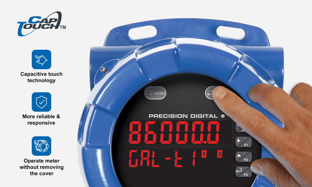
One of the standout features of the PD8-6000 is its user-friendly design. You can program and operate the meter without needing to open the housing. This is made possible by the built-in SafeTouch® through-glass buttons and the RS485 serial communication port, which supports the free Modbus® protocol.
With the Precision Digital ProtEX-MAX™ PD8-6000, you get a reliable and efficient solution for monitoring processes in explosive environments, ensuring safety and ease of use.
General
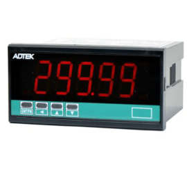
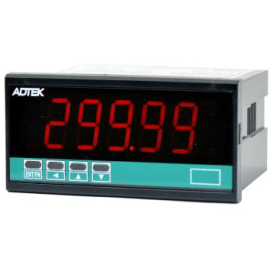
Display: Upper display: 0.60″ (15 mm) high. Lower display: 0.46″ (12 mm) high. Both are 6 digits (-99999 to 999999), red LEDs.
Display Intensity: Eight intensity levels
Display Update Rate: 5/second (200 ms)
Overrange: Display flashes 999999
Underrange: Display flashes -99999
Display Assignment: The upper and lower displays may be assigned to PV1, PV2, PCT (percent), max/min, alternate max & min, set points, units (lower display only), or Modbus input.
Programming Methods: Four through-glass SafeTouch buttons, four mechanical buttons behind glass, digital inputs, PC and MeterView Pro software, or Modbus registers.
F4 Digital Input Contacts: 3.3 VDC on contact. Connect normally open contacts across F4 to COM.
F4 Digital Input Logic Levels: Logic High: 3 to 5 VDC; Logic Low: 0 to 1.25 VDC
Noise filter: Programmable from 2 to 199 (0 will disable filter)
Filter Bypass: Programmable from 0.1 to 99.9% of calibrated span
Recalibration: Calibrated at the factory. Recalibration is recommended at least every 12 months.
Max/Min Display: Max / min readings reached by the process are stored until reset by the user or until power to the meter is turned off.
Password: Three programmable passwords restrict modification of programmed settings.
Non-Volatile Memory: All programmed settings are stored in nonvolatile memory for a minimum of ten years if power is lost.
Power Options: 85-265 VAC 50/60 Hz, 90-265 VDC, 20 W max, or optional sku with 12-24 VDC ±10%, 15 W max.
Fuse: Required external fuse: UL Recognized, 5 A max, slow blow; up to 6 meters may share one 5 A fuse.
Isolated Transmitter Power Supply: Terminals P+ & P-: 24 VDC ± 10%. Isolated from the input at >500 V. Jumper selectable for 24, 10, or 5 VDC supply (internal jumper J4). All skus transmitter supply rated @ 25mA max.
Normal Mode Rejection: Greater than 60 dB at 50/60 Hz
Isolation: 4 kV input/output-to-power line. 500 V input-to-output or output-to-P+ supply.
Overvoltage Category: Installation Overvoltage Category II: Local level with smaller transient overvoltages than Installation Overvoltage Category III.
Environmental: T6 Class operating temperature range Ta = -40 to 60°C
T5 Class operating temperature range Ta = -40 to 65°C
Max Power Dissipation: Maximum power dissipation limited to 15.1 W.
Connections: Removable screw terminal blocks accept 12 to 22 AWG wire, RJ45 for external relays, digital I/O, and serial communication adapters.
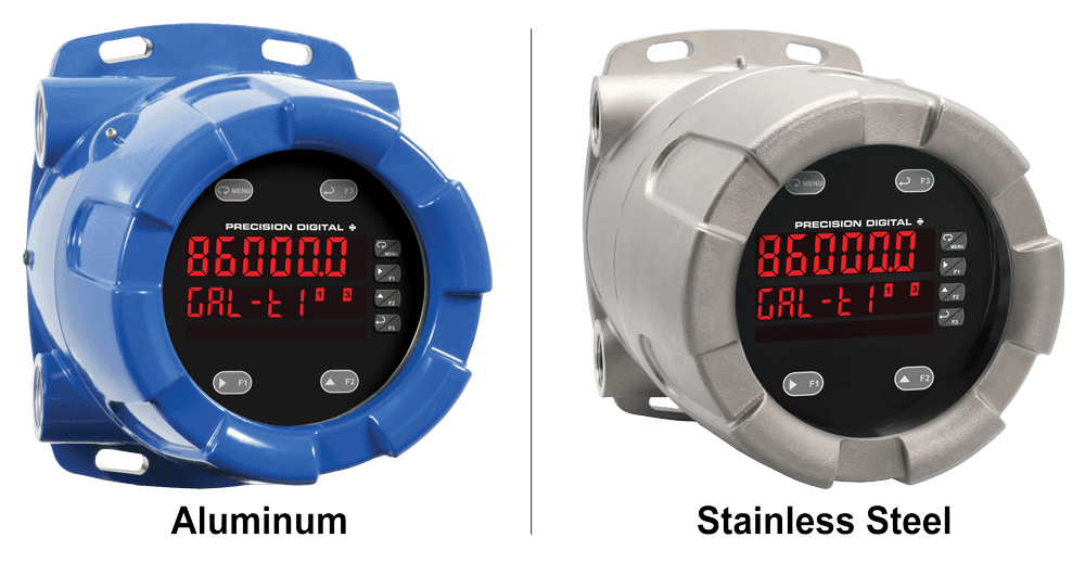
Enclosure: Explosion-proof die cast aluminum with glass window, corrosion resistant epoxy coating, color: blue. NEMA 4X, 7, & 9, IP68. Default conduit connections: Four ¾” NPT threaded conduit openings and two ¾” NPT metal conduit plugs with 12 mm hex key fitting installed. Additional conduit opening configurations may be available; verify quantity and sizes on specific device labeling during installation.
Mounting: Four slotted flanges for wall mounting or NPS 1½” to 2½” or DN 40 to 65 mm pipe mounting.
Dimensions: 6.42″ x 7.97″ x 8.47″ (W x H x D) (163 mm x 202 mm x 215 mm)
Weight: 16.0 lbs (7.26 kg)
Warranty: 3 years parts & labor
USB Connection: Compatibility: USB 2.0 Standard, Compliant
Connector Type: Micro-B receptacle
Cable: USB A Male to Micro-B Cable
Driver: Windows 98/SE, ME, 2000, Server 2003/2008, XP 32/64-Bit,
Vista 32/64-Bit, Windows 7 32/64-Bit, Windows 10 32/64-Bit
Power: USB Port
Process Input
Inputs: Field selectable: 0-20, 4-20 mA, ±10 VDC (0-5, 1-5, 0-10 V), Modbus PV (Slave)
Accuracy: ±0.03% of calibrated span ±1 count, square root & programmable exponent accuracy range: 10-100% of calibrated span
Temperature Drift: 0.005% of calibrated span/°C max from 0 to 65°C ambient, 0.01% of calibrated span/°C max from -40 to 0°C ambient
Signal Input Conditioning: Linear or round horizontal tank volume calculation.
Multi-Point Linearization: 2 to 32 points for PV or PV1. 2 to 8 points for PV2 (Dual-Scale Level feature)
Programmable Exponent: 1.0001 to 2.9999
Low-Flow Cutoff: 0-999999 (0 disables cutoff function)
Decimal Point: Up to five decimal places or none: d.ddddd, dd.dddd, ddd.ddd, dddd.dd, ddddd.d, or dddddd.
Calibration Range: 4-20 mA: minimum span input 1 & input 2: 0.15 mA. ±10 V: minimum span input 1 & 2: 0.10 V. An Error message will appear if input 1 and input 2 signals are too close together.
Input Impedance: Voltage ranges: greater than 1 MΩ. Current ranges: 50 – 100 Ω (depending on resettable fuse impedance).
Input Overload: Current input protected by resettable fuse, 30 VDC max. Fuse resets automatically after fault is removed.
HART Transparency: Analog input will not interfere with existing HART communications on the wired 4-20 mA signal
Relays
Rating: 2 or 4 SPDT (Form C) internal and/or 4 SPST (Form A) external; rated 3 A @ 30 VDC and 125/250 VAC resistive load; 1/14 HP (≈ 50 watts) @ 125/250 VAC for inductive loads such as contactors, solenoids, etc.
Noise Suppression: Noise suppression is recommended for each relay contact switching inductive loads.
Deadband: 0-100% of span, user programmable
High or Low Alarm: User may program any alarm for high or low trip point. Unused alarm LEDs and relays may be disabled (turned off).
Relay Operation: Automatic (non-latching), latching (requires manual acknowledge), sampling (based on time), pump alternation control (2 to 8 relays), Off (disable unused relays and enable interlock feature, manual on/off control mode).
Relay Reset: User selectable via front panel buttons or digital inputs.
1. Automatic reset only (non-latching), when input passes the reset point.
2. Automatic + manual reset at any time (non-latching).
3. Manual reset only, at any time (latching).
4. Manual reset only after alarm condition has cleared (latching).
Note: Front panel button or digital input may be assigned to acknowledge relays programmed for manual reset.
Time Delay: 0 to 999.9 seconds, on & off relay time delays. Programmable and independent for each relay.Fail-Safe Operation: Programmable and independent for each relay.
Note: Relay coil is energized in non-alarm condition. In case of power failure, relay will go to alarm state.
Auto Initialization: When power is applied to the meter, relays will reflect the state of the input to the meter.
Serial Communications
Compatability: EIA-485
Connectors: Removable screw terminal connector
Max Distance: 3,937′ (1,200 m) max
Status Indication: Separate LEDs for Power (P), Transmit (TX), and Receive (RX)
Protocol: Modbus® RTU (Slave Only)
Meter Address/Slave ID: 1 – 247
Baud Rate: 300 – 19,200 bps
Transmit Time Delay: Programmable between 0 and 199 ms or transmitter always on for RS-422 communication
Data: 8 bit (1 start bit, 1 or 2 stop bits)
Parity: Even, odd, or none with 1 or 2 stop bits
Byte-to-Byte Timeout: 0.01 – 2.54 seconds
Turn Around Delay: Less than 2 ms (fixed)
Isolated 4-20 mA Transmitter Output
Output Source: Process variable (PV), max, min, set points 1-8, manual control setting, or Modbus input
Scaling Range: 1.000 to 23.000 mA for any display range
Calibration: Factory calibrated: 4.000 to 20.000 = 4-20 mA output
Analog Output Programming: 23.000 mA maximum for all parameters:Overrange, underrange, max, min, and break
Accuracy: ± 0.1% of span ± 0.004 mA
Temperature Drift: 0.4 µA/°C max from 0 to 65°C ambient, 0.8 µA/°C max from -40 to 0°C ambient
Note: Analog output drift is separate from input drift.
Isolated Transmitter Power Supply: Terminals I+ & R: 24 VDC ± 10%. Isolated from the input at >500 V. May be used to power the 4-20 mA output or other devices. All skus @ 25 mA max.
Output Loop Resistance:
| Power supply | Minimum | Maximum |
| 24 VDC | 10Ω | 700Ω |
| 35 VDC (external) | 100Ω | 1200Ω |
Digital Inputs and Outputs
Channels: 4 digital inputs & 4 digital outputs per module
System: One expansion module may be added for a total of 8 inputs & 8 outputs
Note: The jumper located between the RJ45 connectors must be removed on the expansion module.
Digital Input Logic: High: 3 to 5 VDC;Low: 0 to 1.25 VDC
Digital Output Logic: High: 3.1 to 3.3 VDC; Low: 0 to 0.4 VD
Source Current: 10 mA maximum output current
Sink Current: 1.5 mA minimum input current
+5 V Terminal: To be used as pull-up for digital inputs only. Connect normally open pushbuttons across +5 V & DI 1-4. Warning: DO NOT use +5 V terminal (pin 1) to power external devices.
Function Assignment: The on-board digital inputs (1-4) are designed to mimic the behavior of the front panel buttons (Menu, F1, F2, & F3). If you wish to change their behavior, re-assign F1-F3 to the desired function, then change the corresponding digital input to match.
Product Ratings and Approvals
FM Enclosure:Type 4X; IP66
Class I, Division 1, Groups B, C, D
Class II, Division 1, Groups E, F, G
Class III, Division 1, T5/T6
Class I, Zone 1, AEx d, IIC Gb T5/T6
Zone 21, AEx tb IIIC T90°C; Ta -40°C to +65°C
T6 Ta = -40°C to +60°C; T5 Ta = -40°C to +65°C
Certificate Number: 3047283
CSA: Class I, Division 1, Groups B, C, D
Class II, Division 1, Groups E, F, G
Class III, Division 1
Class I Zone 1 Ex d IIC
Zone 21 Ex tb IIIC T90°C
-40°C < Tamb. < +60° C; Temperature Code T6
-40°C < Tamb. < +65° C; Temperature Code T5
Enclosure Type 4X & IP66
Certificate Number: 2531731
ATEX: II 2 G D Ex d IIC T* Gb
Ex tb IIIC T90°C Db IP68
Ta = -40°C to +*°C
*T6 = -40°C to +60°C
*T5 = -40°C to +65°C
Certificate number: Sira 12ATEX1182
IECEx: Ex d IIC T* Gb
Ex tb IIIC T90°C Db IP68
Ta = -40°C to +*°C
*T6 = -40°C to +60°C
*T5 = -40°C to +65°C
Certificate Number: IECEx SIR 12.0073
Your Complete Solution for Hazardous Area Process Measurement
The PD8-6000 ProtEX-MAX is a high-performance explosion-proof process meter engineered for demanding industrial environments. Built to deliver accuracy, safety, and ease of use, this meter is ideal for hazardous locations where precision and durability are critical.
Safe and Easy Configuration
With CapTouch through-glass technology, operators can program the meter without opening the housing. This allows safe, convenient access to settings even in classified areas.
Integrated Power Supply
The PD8-6000 includes a built-in isolated 24 VDC @ 25 mA power supply for powering transmitters—reducing costs and simplifying installation. Meters with 4-20 mA output options include a second power supply for the output loop.
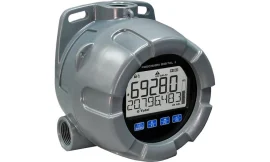
Rugged Design & High-Visibility Display
Housed in explosion-proof aluminum or stainless steel with mounting flanges, the meter features a dual-line 6-digit LED display. The top line displays up to 999,999, while the bottom line can show tags or alternate scales—perfect for tank level monitoring and more.
Key Features
- Four onboard relays and isolated 4–20 mA analog output
- Advanced signal conditioning and automatic tank linearization
- Customizable function keys and pump alternation
- Modbus RTU communication over RS-485
Programming Options
Configuration can be done safely on-site using the CapTouch interface or remotely via MeterView Pro software in a non-hazardous area.
Visual Reference
Front View

Wiring Connections

Transmitter Power Options
Powering Transmitters
The meter provides a selectable 5, 10, or 24 VDC (default) to power transmitters, even when powered by DC supply. Switching to an external supply is as simple as changing terminal connections.

Powering 4-20 mA Output
When using the analog output, a separate 24 VDC @ 25 mA source powers the loop, enabling full loop isolation.
Overload Protection
The input circuit is safeguarded by a resettable fuse that prevents damage from excessive current.
Display Innovations
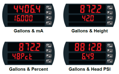
Dual-Line Versatility
The upper display can be set for process variables (PV), peak, valley, alarm states, or Modbus input. The lower display shows engineering units, setpoints, or messages—or can be disabled if not needed.
This dual-display design enhances usability during both setup and daily operation. It supports simultaneous dual-scaling, such as showing both height and volume for level applications.
High-Brightness Readability
Standard ultra-bright LEDs offer excellent visibility, even under direct sunlight. Users can adjust brightness across eight intensity levels.
Programming Made Simple
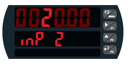
The lower display provides step-by-step prompts during setup, showing both the parameter and current value with highlighted digits for precise editing.
Smooth Display with Rounding
To stabilize fluctuating input signals, the meter can round values based on user-defined steps (1, 2, 5, 10, 20, 50, 100). For example, an input of 12346 rounds to 12350 with a rounding value of 10.
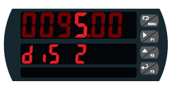
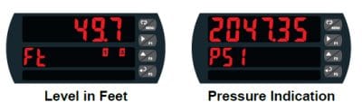
Dual-Scale Display Functionality
The dual-scale mode enables simultaneous display of two differently scaled values derived from the same 4-20 mA input. Common applications include displaying gallons and height, pressure and force, or feet and meters.
MeterView Pro software can configure these dual-scale outputs:

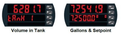
Lower Display Uses
The secondary line can also be used to show engineering units, channel tags, or active setpoints as shown below: