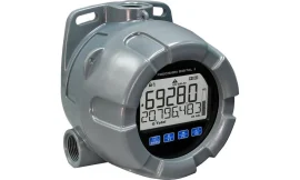
The Precision Digital Helios stands out from other large display meters thanks to its dual line display featuring super bright LEDs. This design ensures that readings are clear and easy to see, even in bright sunlight and from distances of up to 100 feet.
Built on the trusted foundation of Precision Digital’s renowned ProVu® digital panel meters, the Helios is versatile enough to handle a wide range of applications, including level, flow, temperature, pressure, and weight measurements. It supports various input types, such as:
- 4-20 mA
- Thermocouple
- RTD
- Pulse
- Strain gauge
- AC and DC volts and current
- Modbus®
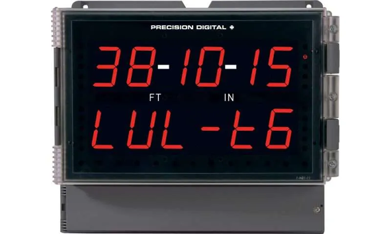
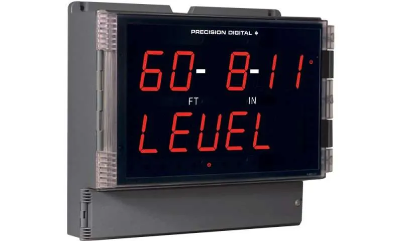
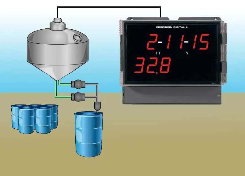
If you need to measure levels in feet and inches, the Helios PD2-6001 is the perfect choice. This model displays measurements up to 99 feet, 11 and 15/16 inches on the upper line, while the lower line can show a tag or volume, even for non-linear tanks like round horizontal ones.
The PD2-6001 is an excellent outdoor tank side indicator. Its bright display is easily readable in direct sunlight, and it operates effectively in temperatures ranging from -40 to 150°F. Additionally, this model can be equipped with a 4-20 mA output and four relays, making it ideal for alarming or controlling applications, such as pump alternation control.
Input
0-20 mA, 4-20 mA, 0-5 V, 1-5 V, and ±10 V
Helios Features
- Large 1.80″ Digits
- Dual Line Display
- Six Full Digits on Each Line
- Readable From 100 Feet Away
- Superluminous Sunlight Readable Display
- NEMA 4X, IP65 Rated Field Mountable Enclosure
- Great for Outdoor Use: -40 to 150°F (-40 to 65°C)
- Program the Meter from a PC with Onboard USB and MeterView® Pro
PD2-6001 Features
- Feet & Inches Display Ideal for Level Applications
- Isolated 24 VDC @ 200 mA Transmitter Power Supply
- Multi-Pump Alternation Control
- Display a Single Input in Two Different Scales (e.g. Height & Volume)
- Signal Input Conditioning for Oddly Shaped and Round Horizontal Tanks
- 32-Point, Square Root, or Exponential Linearization
- Current Input Protected by Resettable Fuse
- Displays Fractions of an Inch as Eighths or Sixteenths
General
Display: Two lines with 1.8″ (46 mm) high digits with feet & Inches designations, red LEDs; 6 digits per line (-99999 to 999999), with lead zero blanking
Feet & Inches Display Range:0″ 00″ 0/16″ to 99″ 11″ 15/16″
Display Intensity: Eight intensity levels
Display Update Rate: 5/second (200 ms)
Overrange: Display flashes 999999
Underrange: Display flashes -99999
Display Assignment: The upper and lower displays may be assigned to PV1, PV2, PCT (percent), d r-u, d gross, d nt-g, max/min, alternate max & min, set points, units (lower display only), or Modbus input.
Programming Methods: Four SafeTouch through-glass buttons when cover is installed. Four internal pushbuttons when cover is removed.
F4 Digital Input Contacts: 3.3 VDC on contact. Connect normally open contacts across F4 to COM.
F4 Digital Input Logic Levels: Logic High: 3 to 5 VDC; Logic Low: 0 to 1.25 VDC
Noise filter: Programmable from 2 to 199 (0 will disable filter)
Filter Bypass: Programmable from 0.1 to 99.9% of calibrated span
Recalibration: Calibrated at the factory. Recalibration is recommended at least every 12 months.
Max/Min Display: Max / min readings reached by the process are stored until reset by the user or until power to the meter is turned off.
Password: Three programmable passwords restrict modification of programmed settings.
Non-Volatile Memory: All programmed settings are stored in nonvolatile memory for a minimum of ten years if power is lost.
Power Options: 85-265 VAC 50/60 Hz, 90-265 VDC, 20 W max or 12-24 VDC ± 10%, 15 W max. Powered over USB for configuration only.
Isolated Transmitter Power Supply: Terminals P+ & P-: 24 VDC ± 10%. 12-24 VDC powered skus selectable for 24, 10, or 5 VDC supply (internal P+/P- switch). 85-265 VAC skus rated @ 200 mA max, 12-24 VDC powered skus rated @ 100 mA max, @ 50 mA max for 5 or 10 VDC supply.
Fuse: Required external fuse: UL Recognized, 5 A max, slow blow; up to 6 meters may share one 5 A fuse.
Isolation: 4 kV input/output-to-power line. 500 V input-to-output or output-to-P+ supply.
Overvoltage Category: Installation Overvoltage Category II: Local level with smaller transient overvoltages than Installation Overvoltage Category III.
Environmental:
T6 Class operating temperature range Ta = -40 to 60°C
T5 Class operating temperature range Ta = -40 to 65°C
See LIM8 ProtEX-MAX instruction manual for additional details.
Max Power Dissipation: Maximum power dissipation limited to 15.1 W. See PD8 instruction manual for additional details.
Connections: Removable screw terminal blocks accept 12 to 22 AWG wire, RJ45 for external relays, digital I/O, and serial communication adapters.
Enclosure: UL Type 4X, IP65 rated. Polycarbonate & glass blended plastic case, color: gray. Includes four PG11 through-hole conduit openings, with two factory installed PG11, IP68, black nylon threaded hole plugs with backing nuts.
Wall Mounting: Four (4) mounting holes provided for mounting meter to wall.
Pipe Mounting: Optional pipe mounting kit (PDA6260) allows for pipe mounting. Sold separately.
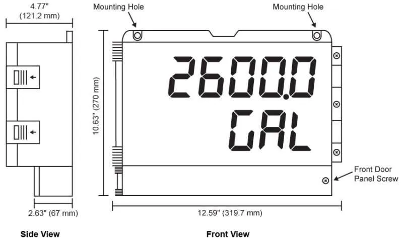
See PD2-6001 manual for instructions.Dimensions: 10.63″ x 12.59″ x 4.77″ (270 mm x 319.7 mm x 121.2 mm) (H x W x D)
Weight: 6.10 lbs (2.76 kg)
UL File Number: UL & C-UL Listed. E160849; 508 Industrial Control Equipment.
Warranty: 3 years parts & labor
USB Connection: Compatibility: USB 2.0 Standard, Compliant Connector Type: Micro-B receptacle Cable: USB A Male to Micro-B Cable Driver: Windows 98/SE, ME, 2000, Server 2003/2008, XP 32/64-Bit, Vista 32/64-Bit, Windows 7 32/64-Bit, Windows 10 32/64-Bit Power: USB Port
Process Input
Inputs: Field selectable: 0-20, 4-20 mA, ±10 VDC (0-5, 1-5, 0-10 V), Modbus PV (Slave)
Accuracy: ±0.03% of calibrated span ±1 count, square root & programmable exponent accuracy range: 10-100% of calibrated span
Temperature Drift: 0.005% of calibrated span/°C max from 0 to 65°C ambient, 0.01% of calibrated span/°C max from -40 to 0°C ambient
Signal Input Conditioning: Linear, square root, programmable exponent, or round horizontal tank volume calculation.
Multi-Point Linearization: 2 to 32 points for PV or PV1. 2 to 8 points for PV2 (Dual-Scale Level feature)
Programmable Exponent: 1.0001 to 2.9999
Low-Flow Cutoff: 0-999999 (0 disables cutoff function)
Decimal Point: Up to five decimal places or none: d.ddddd, dd.dddd,ddd.ddd, dddd.dd, ddddd.d, or dddddd.
Calibration Range: 4-20 mA: minimum span input 1 & input 2: 0.15 mA. ±10 V: minimum span input 1 & 2: 0.10 V. An Error message will appear if input 1 and input 2 signals are too close together.
Input Impedance: Voltage ranges: greater than 1 MΩ. Current ranges: 50 – 100 Ω (depending on resettable fuse impedance).
Input Overload:Current input protected by resettable fuse, 30 VDC max.
HART Transparency: Analog input will not interfere with existing HART communications on the wired 4-20 mA signal
Relays
Rating: 2 or 4 SPDT (Form C) internal and/or 4 SPST (Form A) external; rated 3 A @ 30 VDC and 125/250 VAC resistive load; 1/14 HP (≈ 50 watts) @ 125/250 VAC for inductive loads such as contactors, solenoids, etc.
Noise Suppression: Noise suppression is recommended for each relay contact switching inductive loads.
Deadband: 0-100% of span, user programmable
High or Low Alarm: User may program any alarm for high or low trip point. Unused alarm LEDs and relays may be disabled (turned off).
Relay Operation: automatic (non-latching), latching (requires manual acknowledge), sampling (based on time), pump alternation control (2 to 8 relays), Off (disable unused relays and enable interlock feature, manual on/off control mode).
Relay Reset: User selectable via front panel buttons or digital inputs.
1. Automatic reset only (non-latching), when input passes the reset point.
2. Automatic + manual reset at any time (non-latching).
3. Manual reset only, at any time (latching).
4. Manual reset only after alarm condition has cleared (latching).
Note: Front panel button or digital input may be assigned to acknowledge relays programmed for manual reset.
Time Delay: 0 to 999.9 seconds, on & off relay time delays. Programmable and independent for each relay.
Fail-Safe Operation: Programmable and independent for each relay.
Note: Relay coil is energized in non-alarm condition. In case of power failure, relay will go to alarm state.
Auto Initialization:When power is applied to the meter, relays will reflect the state of the input to the meter.
Serial Communications
Compatability: EIA-485
Connectors: Removable screw terminal connector
Max Distance: 3,937′ (1,200 m) max
Status Indication: Separate LEDs for Power (P), Transmit (TX), and Receive (RX)
Protocol:Modbus® RTU
Meter Address/Slave ID: 1 – 247
Baud Rate: 300 – 19,200 bps
Transmit Time Delay: Programmable between 0 and 199 ms or transmitter always on for RS-422 communication
Data: 8 bit (1 start bit, 1 or 2 stop bits)
Parity: Even, odd, or none with 1 or 2 stop bits
Byte-to-Byte Timeout: 0.01 – 2.54 seconds
Turn Around Delay: Less than 2 ms (fixed)
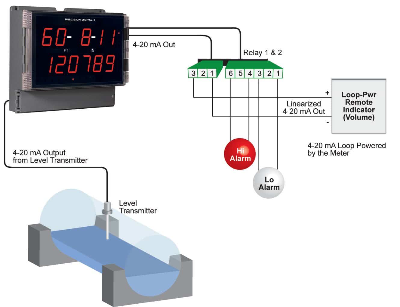
Isolated 4-20 mA Transmitter Output
Output Source: Process variable (PV), max, min, set points 1-8, manual control setting, or Modbus input
Scaling Range: 1.000 to 23.000 mA for any display range
Calibration: Factory calibrated: 4.000 to 20.000 = 4-20 mA output
Analog Output Programming: 23.000 mA maximum for all parameters:
Overrange, underrange, max, min, and break
Accuracy: ± 0.1% of span ± 0.004 mA
Temperature Drift: 0.4 µA/°C max from 0 to 65°C ambient, 0.8 µA/°C max from -40 to 0°C ambient
Note: Analog output drift is separate from input drift.
Isolated Transmitter Power Supply: Terminals I+ & R: 24 VDC ± 10%. Isolated from the input at >500 V. May be used to power the 4-20 mA output or other devices. All skus rated @ 40 mA max.
Output Loop Resistance:
| Power supply | Minimum | Maximum |
| 24 VDC | 10Ω | 700Ω |
| 35 VDC (external) | 100Ω | 1200Ω |
Digital Inputs and Outputs
Channels: 4 digital inputs & 4 digital outputs per module
System: One expansion module may be added for a total of 8 inputs & 8 outputs
Note: The jumper located between the RJ45 connectors must be removed on the expansion module.
Digital Input Logic: High: 3 to 5 VDC; Low: 0 to 1.25 VDC
Digital Output Logic: High: 3.1 to 3.3 VDC; Low: 0 to 0.4 VD
Source Current: 10 mA maximum output current
Sink Current: 1.5 mA minimum input current
+5 V Terminal: To be used as a pull-up for digital inputs only. Connect normally open pushbuttons across +5 V & DI 1-4. Warning: DO NOT use +5 V terminal (pin 1) to power external devices.
Function Assignment: The onboard digital inputs (1-4) are designed to mimic the behavior of the front panel buttons (Menu, F1, F2, & F3). If you wish to change their behavior, re-assign F1-F3 to the desired function, then change the corresponding digital input to match.
4-Relay Expansion Module
Relays: Four Form A (SPST) rated 3 A @ 30 VDC and 125/250 VAC resistive load; 1/14 HP (approx. 50 watts) @ 125/250 VAC for inductive load
Dimensions
Wall Mounting
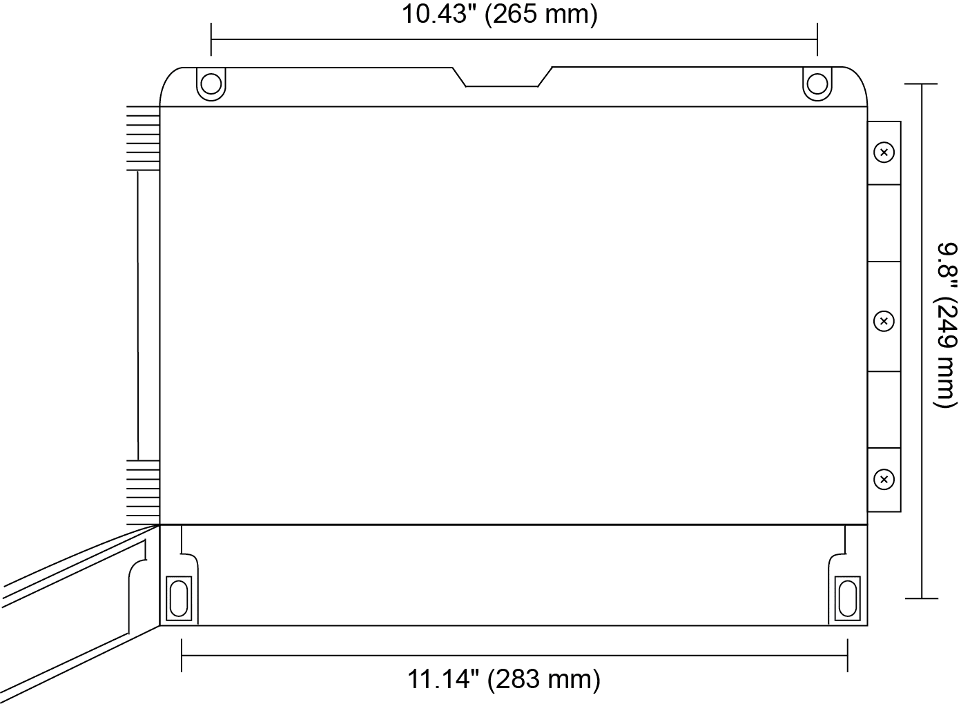
The meter can be mounted to any wall using the four provided mounting holes. Note that the bottom mounting holes are located underneath the front door panel. To mount the meter to a wall, follow these instructions.
- Prepare a section of wall approximately 11″ x 13″ (280 mm x 330 mm) for meter mounting by marking with a pencil the mounting holes (shown in the image to the right) on the wall.
- Using a drill bit slightly smaller than the girth of the mounting screws, pre-drill holes at the mounting locations previously marked.
- Insert mounting screws into the four mounting holes and screw them into the pre-drilled holes. Do not overtighten the mounting screws as it is possible that the enclosure could crack and become damaged.

Meter Mounting Holes
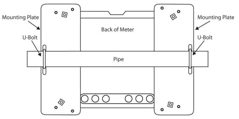
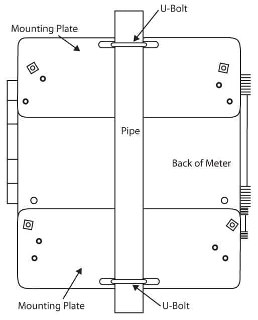
Pipe Mounting
The meter can also be mounted to a pipe using the optional pipe mounting kit (PDA6260)…
- Secure the mounting plates to the top and bottom (for vertical pipes) or left and right (for horizontal pipes)…
- Using the provided nuts and U-bolts, secure the mounting plates to the pipe…

Horizontal Pipe Mount Assembly

Vertical Pipe Mount Assembly
Applications
Signal Input Conditioning
Non-linear input signals can be linearized…

8-Point Linearizer for Volume

Round Horizontal Tank Signal Input Conditioner
Multi-Pump Alternation
For pump control applications…
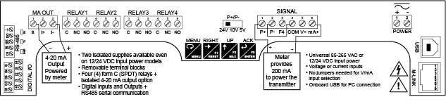
Connections Labeling
The connectors’ label…
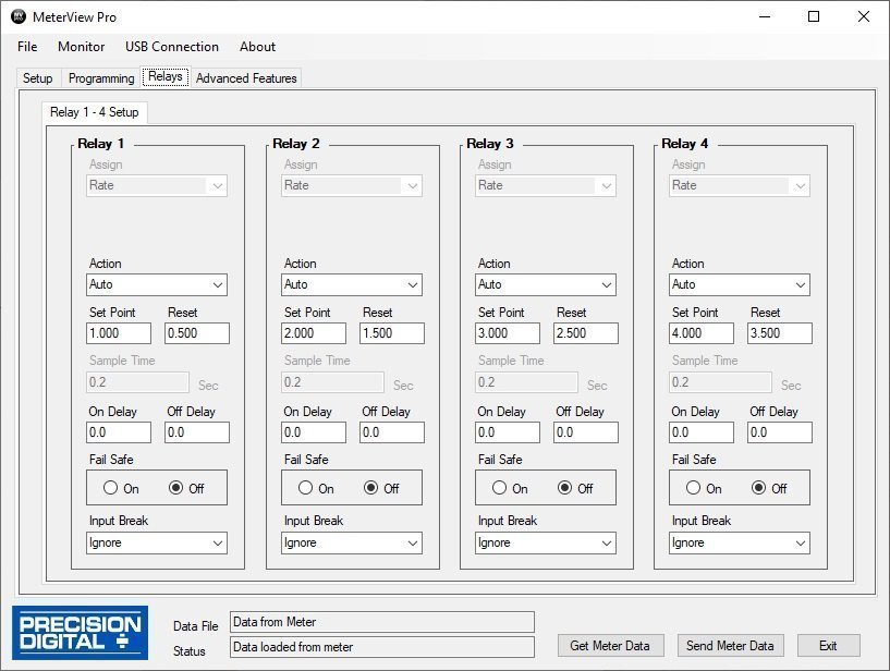
MeterView® Pro Software
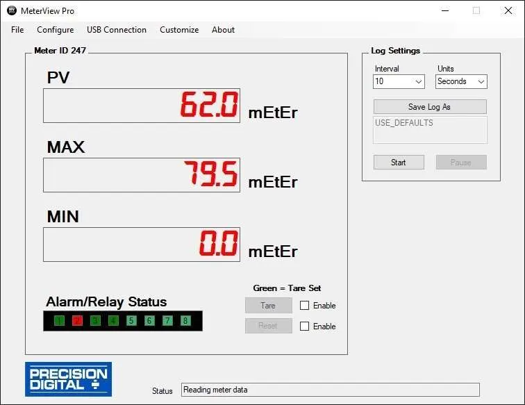
MeterView® Pro software is designed for use with ProVu…
- Go to the Diagnostics menu

- Scroll to Info menu
- Press Enter to view version info
Monitor and Datalog

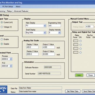
Setup

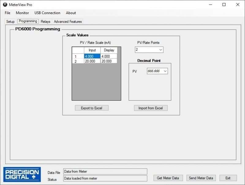
Programming

Relays