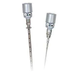
| Fine-Tek JTR Guided Wave Radar Level Transmitter |
| ● GENERAL DESCRIPTION |
| Type | Guided Wave Radar (GWR) Level Transmitter, time-domain reflectometry / contact-type microwave pulse level meter |
| Model Series Covered | JTR301 (Rod / Steel wire cable type, liquid), JTR302 (Rod / Steel wire cable type, solid), JTR305 (Coaxial type, low-dielectric liquid), JTR30A (Sanitary rod type, liquid or solid) |
| Operating Principle | Transmits electromagnetic (microwave) pulses along a steel wire cable or rod probe. When the pulses encounter the surface of the medium being measured, part of the pulse is reflected back to the instrument along the same path as an echo wave; the time-of-flight is used to calculate the level height. |
| Measuring Capability | Solid and liquid level measurement, including low dielectric constant solid bulk materials; capable of measuring solid level, liquid level, and medium interface (dual liquid level interface measurement) |
| Display | 128 x 64 LCM display; shows distance, level, percentage, and 4~20 mA current; on-site adjustment; echo wave graphics display for signal waveform inside the tank (background noise processing) |
| Interface Language | Traditional Chinese, Simplified Chinese, English (selectable) |
| Special Functions | Simulated 4 mA / 20 mA output current signal; save background noise function to eliminate fake echoes; internal automatic temperature compensation; bottom signal enhancement & tracking technology for low dielectric constant media; dual liquid level interface measurement (with separate-layer interface setting) |
| Power Consumption | 2.4 W max. (2-wire, 4~20 mA) |
| Application Areas | Power plant, Chemical plant, Cement plant, Water treatment, Paper mill plant, Steel plant, Refinery plant |
| |
| ● MATERIALS |
| Housing Material | Aluminum alloy (all models) |
| Probe Material (selectable, per order code) | MA: SUS 304 | MC: SUS 316L |
| Protection Rating | IP67 (all models) |
| |
| ● ELECTRICAL / PERFORMANCE RATINGS (common to JTR301 / JTR302 / JTR305 / JTR30A) |
| Accuracy | ±5mm or ±0.1% F.S., whichever is greater |
| Repeatability | ±3mm or ±0.05% F.S., whichever is greater |
| Power Supply | 16~30 Vdc Loop Power (2-wire); 16~30 Vdc (4-wire); 5~10 Vdc RS485-only variant (JTR30XF) |
| Analog Output | 4~20 mA |
| Current Distinguishability | 1.6 uA |
| Load Impedance | (Vs-16)/0.022 Ohm for 2-Wire; 300 Ohm for 4-Wire > 16V |
| Digital Communication | HART 7.0 for 2-Wire; RS485 (Modbus) for 4-Wire |
| Ambient Temperature | -40~80°C (general); for Ex-proof units (ATEX / CSA / IECEx): -40~80°C, NEPSI: -40~60°C |
| Operating Pressure | 0~60 Bar (at 25°C) |
| Test Standards | | High voltage | IEC60947-2 | | Insulation resistance | IEC60092-504 | | Power supply variation | IEC60092-504 | | Power supply failure | IEC60092-504 | | Electrical burst testing | IEC61000-4-4 | | Voltage DIPS | IEC61000-4-11 | | Humidity | IEC60068-2-30 | | High/Low temperature test | IEC60068-2-38 | | IP protection rating | IEC60529 |
|
| |
| ● MEASURING RANGE BY DIELECTRIC CONSTANT |
| JTR301 / JTR305 | | Dielectric constant (εr) | Typical liquids (examples) | Steel wire cable type | Rod type | Coaxial type | | 1.6~2.0 | Liquefied gas (e.g. propane), Solvent, Freon, Palm oil | Needs special model with S5 type float | 6m | | 2.0~2.5 | Mineral oils, fuels | 12m | 6m | 6m | | 2.5~4.0 | Benzene, styrene, toluene, Furan, Naphthalene | 14m | 6m | 6m | | 4.0~7.0 | Chlorobenzene, chloroform, Cellulose spray, Isocyanate, aniline | 16m | 6m | 6m | | > 7.0 | Aqueous solutions, Alcohols, Ammonia | 20m | 6m | 6m | | JTR302 | | Dielectric constant (εr) | Typical materials (examples) | Steel wire cable type | Rod type | | 2.0~2.5 | Portland cement, Plaster, Plastic granulate | 12m | 6m | | 2.5~4.0 | Grain, seeds, Flour, Ground stones, Sand | 14m | 6m | | 4.0~7.0 | Naturally moist stones, ores, Salt | 16m | 6m | | > 7.0 | Metallic powder, Carbon black, Coal | 20m | 6m |
|
| |
| ● DIMENSIONS (Unit: mm) & MODEL-SPECIFIC RATINGS |
| JTR301 — Medium: Liquid — Min. Dielectric: 2.0 — Minimum connection: 3/4″PF | | Parameter | Standard type | High temp. type | | Operating temperature | -40~150°C | -40~230°C | | Measuring range | Rod type: 6m | Cable type: up to 20m (dielectric-dependent, see Measuring Range table) | | Housing / conduit entry | Housing φ84mm, height 139mm, 1/2″PF conduit entry (both types) | | Standoff height (housing base to flange) | 49mm | 125mm + 49mm (extended standoff) | | Flange thread | 3/4″PF, flange depth 25mm | | Probe type / diameter | Rod type: φ6mm | Cable type: φ4mm | | Probe length range | Rod type: 500~6000mm | Cable type: 500~20000mm | | Cable-type bottom weight | φ20mm x 150mm, M12xP1.25 threaded weight | | Dead band | High const. (ε>10): Upper <100mm, Lower <50mm
Low const. (ε<10): Upper <500mm, Lower <100mm | High const. (ε>10): Upper <300mm, Lower <50mm
Low const. (ε<10): Upper <500mm, Lower <100mm | | JTR302 — Medium: Solid — Min. Dielectric: 2.0 — Minimum connection: 1-1/2″PF | | Parameter | Standard type | High temp. type | | Operating temperature | -40~150°C | -40~230°C | | Measuring range | Rod type: 6m | Steel wire cable type: up to 20m (dielectric-dependent, see Measuring Range table) | | Housing / conduit entry | Housing φ84mm, height 139mm, 1/2″PF conduit entry (both types) | | Standoff height (housing base to flange) | 51mm | 125mm + 51mm (extended standoff) | | Flange thread | 1-1/2″PF, flange depth 25mm | | Probe type / diameter | Rod type: φ10mm | Steel wire cable type: φ6mm | | Probe length range | Rod type: 500~6000mm | Cable type: 500~20000mm | | Cable-type bottom weight | φ38mm x 150mm, M12xP1.25 threaded weight | | Dead band | High const. (ε>10): Upper <100mm, Lower <50mm
Low const. (ε<10): Upper <500mm, Lower <100mm | High const. (ε>10): Upper <300mm, Lower <50mm
Low const. (ε<10): Upper <500mm, Lower <100mm | | JTR305 — Coaxial type — Medium: Low Dielectric Liquid — Min. Dielectric: 1.6 — Minimum connection: 3/4″PF | | Parameter | Standard type | High temp. type | | Operating temperature | -40~150°C | -40~230°C | | Measuring range | 6m (fixed) | | Housing / conduit entry | Housing φ84mm, height 139mm, 1/2″PF conduit entry (both types) | | Standoff height (housing base to flange) | 49mm | 125mm + 49mm (extended standoff) | | Flange thread | 3/4″PF, flange depth 37.2mm | | Coaxial probe diameter | Outer tube φ37.2mm / inner rod φ21.7mm | | Probe length range | 500~6000mm | | Dead band (applies to both types, per source datasheet) | High const. (ε>10): Upper <100mm, Lower <50mm
Low const. (ε<10): Upper <500mm, Lower <100mm | | JTR30A — Sanitary Rod type — Min. Dielectric: 1.6 | | Parameter | Standard type | High temp. type | | Operating temperature | -40~150°C | -40~230°C | | Measuring range | 6m (fixed, both media) | | Medium / Connection / Probe dia. | Liquid: 1″(3A) connection, φ6mm rod | Solid: 2″(3A) connection, φ10mm rod | | Housing / conduit entry | Housing φ84mm, height 139mm, 1/2″PF conduit entry (both types) | | Standoff height (housing base to fitting) | 49mm (1″) / 51mm (2″) | 125mm + 49mm (1″) / 125mm + 51mm (2″) | | Fitting depth | 25mm | | Probe length range | 500~6000mm | | Dead band | High const. (ε>10): Upper <100mm, Lower <50mm
Low const. (ε<10): Upper <500mm, Lower <100mm | High const. (ε>10): Upper <300mm, Lower <50mm
Low const. (ε<10): Upper <500mm, Lower <100mm |
|
| Note: The measuring range is referenced from the flange/thread contact surface (reference plane) to the bottom of the induction rod, minus the upper and lower dead (blind) bands. Default measuring range is factory-set using water as the test medium. |
| |
| ● WIRING / CONNECTIONS |
| JTR30XB (2-wire, single loop) | Loop power 16~30Vdc with HART via terminals V+, V- |
| JTR30XD (2-wire, dual loop) | Two independent loop-power circuits with HART, via terminal blocks J1 (V1+, V1-) and J2 (V2+, V2-), each 16~30Vdc. Note: when equipped with two sets of analog outputs, each circuit must be operated independently — parallel connection of the two circuits will cause abnormal current output. |
| JTR30XH (4-wire, dual analog out) | 4-wire 16~30Vdc, dual 4~20mA analog outputs (I+/I-, I2+/I2-) with RS485, power/communication via terminals D+/D-, V+/V- |
| JTR30XE (4-wire, single analog out) | 4-wire 16~30Vdc, single 4~20mA analog output (I+/I-) with RS485, via terminals D+/D-, I+/I-, V+/V- |
| JTR30XF (4-wire, RS485 only) | 4-wire 5~10Vdc, RS485 communication only (no analog output), via terminals D+/D-, V+/V- |
| Shielding | All wiring configurations use a shielded cable connection to the power/signal source |
| Installation Clearance | Metal container: min. 300mm (12in) spacing from other devices in the container. Non-metal container: min. 500mm (19.7in) spacing from container wall. Probe must not touch any device or tank wall during operation. |
| |
| ● INTRINSICALLY SAFE PARAMETERS (option) |
| Applicable to ATEX / CSA / IECEx / NEPSI intrinsically-safe (Ex ia) certified units. Must be combined with an ex-proof safety barrier/fence meeting level Ex ia to form the complete intrinsically safe system. |
| ATEX / CSA / IECEx / TS | | Model series | Power circuit | Input entity parameters | Output entity parameters | | JTR30XD | Loop power 16~30Vdc x2 with HART, 2-core wire via terminal blocks J1 and J2 | Loop Power 1 In (V1+,V1-) & Loop Power 2 In (V2+,V2-): Ui=30V, Ii=100mA, Pi=0.7W, Ci=0, Li=0 | None | | JTR30XB | Loop power 16~30Vdc with HART, 2-core wire via terminal block J1 | Loop Power In (V+,V-): Ui=30V, Ii=100mA, Pi=0.7W, Ci=0, Li=0 | None | | JTR30XH | 4-Wire 16~30Vdc 4~20mA with RS485, 2-core wire via terminal blocks J1 and J4 | RS-485 In (D+,D-): Ui=12V, Ii=100mA, Pi=0.3W, Ci=0, Li=0. Power In (V+,V-): Ui=30V, Ii=100mA, Pi=0.7W, Ci=0, Li=0. (RS-485 In feedback: Uo=5.88V, Io=12.5mA, Po=18.5mW, Co=43µF, Lo=3555µH) | Analog Out 1 (I+,I-) via J2 & Analog Out 2 (I2+,I2-) via J3: Uo=13.65V, Io=69mA, Po=0.236W, Co=0.79µF, Lo=7468µH (each) | | JTR30XE | 4-Wire 16~30Vdc 4~20mA with RS485, 2-core wire via terminal blocks J1 and J4 | RS-485 In (D+,D-): Ui=12V, Ii=100mA, Pi=0.3W, Ci=0, Li=0. Power In (V+,V-): Ui=30V, Ii=100mA, Pi=0.7W, Ci=0, Li=0. (RS-485 In feedback: Uo=5.88V, Io=12.5mA, Po=18.5mW, Co=43µF, Lo=3555µH) | Analog Out 1 (I+,I-) via J2: Uo=13.65V, Io=69mA, Po=0.236W, Co=0.79µF, Lo=7468µH | | JTR30XF | 4-Wire 5Vdc with RS485, 2-core wire via terminal blocks J1 and J4 | RS-485 In (D+,D-): Ui=12V, Ii=100mA, Pi=0.3W, Ci=0, Li=0. Power In (V+,V-): Ui=10V, Ii=300mA, Pi=0.7W, Ci=0, Li=0. (RS-485 In feedback: Uo=5.88V, Io=12.5mA, Po=18.5mW, Co=43µF, Lo=3555µH) | None |
|
| <td col |