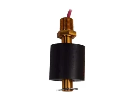
| Fine-Tek FFX Side Mounting Float Switch |
| ● GENERAL DESCRIPTION |
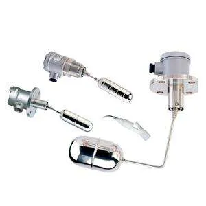
| Type | Side-mounted (horizontal) float level switch for tanks or vessels, used as high or low level control |
| Working Principle | Reed switch type relies on buoyancy and magnetism. The float (containing a magnet) rises and falls with liquid level; the pivot arm’s magnet repels the stationary stem’s switch magnet, opening or closing the electrical circuit. Micro-switch types operate the same buoyancy/pivot mechanism but actuate a mechanical microswitch instead of a reed switch. |
| Switch Technology Options | Micro-Switch type or Reed Switch type |
| Mounting | Custom-made mounting flanges (JIS, DIN, ANSI) or threaded connection |
| Float Selection | Wide variety of floats available for different liquid specific gravities (S.G.) |
| Construction Variants | Standard, Mini, Anti-Corrosive, Vertical, Double angle, Square flange (with/without test accessories), Small, and dual-switch variants of Standard/Vertical/Double angle/Square flange |
| |
| ● MATERIALS |
| Wetted Parts (Order code 19-20) | MA: SUS304 | MB: SUS316 | MC: SUS316L | 18: PP |
| Housing Materials | Aluminum Alloy, IP65 (most Standard/Vertical/Double-angle/Square-flange models); SUS304, IP65 (FF15HEQ); SUS316, Ex d / Ex tb explosion-proof rated (FF70/71 and FF73-75 series); PC (polycarbonate), IP65 (FF80EFM, anti-corrosive); FF81E supplied without housing (wetted parts P.P.) |
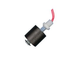
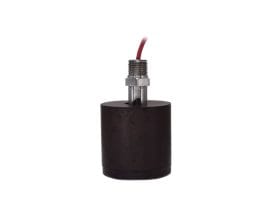
| Anti-Corrosive Model Wetted Parts | P.P. (FF80EFM, FF81E) |
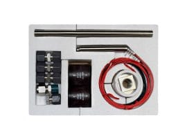
| Test Board Material | SS41 (optional accessory) |
| Material Restriction | SUS304/SUS316 materials are not available for corrosive applications |
| |
| ● ELECTRICAL / PERFORMANCE RATINGS |
| Reed Switch Contact Capacity | 1A, 60W, 220Vac/200Vdc (FF29, FF45, FF55 references); 1A, 50W, 220Vac/200Vdc (FF30, SPST); 1A, 30W, 220Vac/200Vdc (FF89 reference) |
| Micro Switch Contact Capacity | 5A/250Vac (FF19, FF40, FF50, FF90, FF62 references); 3A/250Vac (FF79 reference / explosion-proof SUS316 series) |
| Cable Spec (anti-corrosive models) | PVC, 3 x 0.75 mm² |
| FF90CLO Reference Ratings | Operation pressure: 15 kg/cm²; Weight (approx.): 1.2 kg; Suitable S.G.: greater than 0.65 |
| Model | Operating Temp. | Electrical Contact | Contact Capacity | Contact Element | Housing Spec. | Applicable S.G. | | FF10BHM (UL) | -20~100°C | SPDT(1C) | 5A/250Vac | Microswitch | Aluminum Alloy, IP65 | 0.25 | | FF10CEM (UL) | -20~100°C | SPDT(1C) | 5A/250Vac | Microswitch | Aluminum Alloy, IP65 | 0.65 | | FF10CEQ (UL) | -20~100°C | SPDT(1C) | 5A/250Vac | Microswitch | Aluminum Alloy, IP65 | 0.65 | | FF10CLO (UL) | -20~100°C | SPDT(1C) | 5A/250Vac | Microswitch | Aluminum Alloy, IP65 | 0.65 | | FF10DFM (UL) | -20~100°C | SPDT(1C) | 5A/250Vac | Microswitch | Aluminum Alloy, IP65 | 0.55 | | FF10DFQ (UL) | -20~100°C | SPDT(1C) | 5A/250Vac | Microswitch | Aluminum Alloy, IP65 | 0.55 | | FF15HEQ | -20~100°C | SPDT(1C) | 5A/250Vac | Microswitch | SUS304, IP65 | 0.8 | | FF12CEM | -40~100°C | SPDT(1C) x2 | 5A/250Vac | Microswitch | Aluminum Alloy, IP65 | 0.65 | | FF20BHM | -40~200°C | SPDT(1C) | 1A, 60W, 220Vac/200Vdc | Reed Switch | Aluminum Alloy, IP65 | 0.25 | | FF20CEM | -40~200°C | SPDT(1C) | 1A, 60W, 220Vac/200Vdc | Reed Switch | Aluminum Alloy, IP65 | 0.65 | | FF20CEQ | -40~200°C | SPDT(1C) | 1A, 60W, 220Vac/200Vdc | Reed Switch | Aluminum Alloy, IP65 | 0.65 | | FF20DFM | -40~200°C | SPDT(1C) | 1A, 60W, 220Vac/200Vdc | Reed Switch | Aluminum Alloy, IP65 | 0.55 | | FF20DFQ | -40~200°C | SPDT(1C) | 1A, 60W, 220Vac/200Vdc | Reed Switch | Aluminum Alloy, IP65 | 0.55 | | FF20DLO | -40~200°C | SPDT(1C) | 1A, 60W, 220Vac/200Vdc | Reed Switch | Aluminum Alloy, IP65 | 0.55 | | FF40DFM | -20~100°C | SPDT(1C) | 5A/250Vac | Microswitch | Aluminum Alloy, IP65 | 0.55 | | FF45DFM | -40~200°C | SPDT(1C) | 1A, 60W, 220Vac/200Vdc | Reed Switch | Aluminum Alloy, IP65 | 0.55 | | FF50DFM | -20~100°C | SPDT(1C) | 5A/250Vac | Microswitch | Aluminum Alloy, IP65 | 0.55 | | FF55DFM | -40~200°C | SPDT(1C) | 1A, 60W, 220Vac/200Vdc | Reed switch | Aluminum Alloy, IP65 | 0.55 | | FF70/71BHM (Ex-proof) | -20~100°C | SPDT(1C) | 3A/250Vac | Microswitch | SUS316, Ex d / Ex tb | 0.25 | | FF70/71CFM (Ex-proof) | -20~100°C | SPDT(1C) | 3A/250Vac | Microswitch | SUS316, Ex d / Ex tb | 0.65 | | FF70/71DFM (Ex-proof) | -20~100°C | SPDT(1C) | 3A/250Vac | Microswitch | SUS316, Ex d / Ex tb | 0.55 | | FF73GLO (Ex-proof) | -20~100°C | SPDT(1C) | 3A/250Vac | Microswitch | SUS316, Ex d / Ex tb | 0.7 | | FF75DFM (Ex-proof) | -20~100°C | SPDT(1C) | 3A/250Vac | Microswitch | SUS316, Ex d / Ex tb | 0.55 | | FF90CLO (UL) | -20~100°C | SPDT(1C) | 5A/250Vac | Microswitch | Aluminum Alloy, IP65 | 0.65 | | FF30A3Q | -20~100°C | SPST(1A) | 1A, 50W, 220Vac/200Vdc | Reed Switch | SUS304, IP65 | 0.65 | | FF62DFM | -40~350°C | SPDT(1C) | 5A/250Vac | Microswitch | Aluminum Alloy, IP65 | 0.55 | | FF80EFM (anti-corrosive) | -20~80°C | SPDT(1C) | 1A, 30W, 220Vac/200Vdc | Reed switch | PC, IP65 | 0.60 | | FF81E (anti-corrosive, no housing) | -20~80°C | SPDT(1C) | 1A, 30W, 220Vac/200Vdc | Reed switch | Not specified in source (no housing) | 0.60 |
|
| Note: models listed with “(UL)” and the FF70/71/73/75-series “(Ex-proof)” models are additionally approved by class societies DNV-GL, LR, BV, ABS as noted on the source specification pages. |
| |
| ● DIMENSIONS |
| Float Sizes | φ41 x 150L, φ50 x 150L, φ75 x 120L (per nozzle-length chart below); order-code float types also include φ32.5×68, φ75×120, φ41×150, φ50×150, φ44×50(PP), φ41×100, φ41×125 |
| Recommended Maximum Nozzle Length (mm) | See table below (pipe inner diameter A vs. flange-connection max. B and screw-connection max. C, per float diameter). ⊕ = float diameter larger than nozzle diameter, sensor cannot be inserted. ◎ = nozzle length not limited. |
| Pipe Inner Dia. (A) | Float φ41x150L | Float φ50x150L | Float φ75x120L | | Flange (B) max. | Screw (C) max. | Flange (B) max. | Screw (C) max. | Flange (B) max. | Screw (C) max. | | 45 | 102 | 91 | ⊕ | ⊕ | ⊕ | ⊕ | | 50 | 103 | 92 | 102 | 91 | ⊕ | ⊕ | | 55 | 105 | 94 | 103 | 92 | ⊕ | ⊕ | | 60 | 108 | 97 | 106 | 95 | ⊕ | ⊕ | | 65 | 112 | 101 | 107 | 96 | ⊕ | ⊕ | | 70 | 122 | 111 | 110 | 99 | ⊕ | ⊕ | | 75 | 135 | 124 | 114 | 103 | 106 | 95 | | 80 | 148 | 137 | 124 | 113 | 107 | 96 | | 85 | 161 | 150 | 137 | 126 | 109 | 98 | | 90 | 170 | 159 | 150 | 139 | 112 | 101 | | 95 | 186 | 175 | 163 | 152 | 115 | 104 | | 100 | 199 | 188 | 169 | 158 | 119 | 108 | | 105 | 212 | 201 | 188 | 177 | 125 | 114 | | 110 | 225 | 214 | 201 | 190 | 136 | 125 | | 115 | ◎ | ◎ | 214 | 203 | 149 | 138 | | 120 | ◎ | ◎ | ◎ | ◎ | 162 | 151 | | 125 | ◎ | ◎ | ◎ | ◎ | 174 | 163 | | 130 | ◎ | ◎ | ◎ | ◎ | ◎ | ◎ |
|
| Probe/Cable Length Options | 0000: Standard | 0250~0800: 250~800 mm | 0270~1000: 270~1000 mm | 0155~0600: 155~600 mm |
| Vertical/Double-Angle Models (FF40/45/50/55/71/74/75 etc.) | X, Y, Z legs each ≥ 40 mm; sum of legs constraint X+Y+Z ≤ 500 mm (dual-angle types) or X+Y ≤ 1000 mm (single vertical types) per model drawing — exact values not tabulated in source beyond these constraints |
| |