Precision Digital PDW90 Point-to-Multipoint Wireless Process Signal System

SKU: PDW90 Category:

Email Us: sales@mycelectric.com
WhatsApp Us: +6016-551 9084
WhatsApp Channel: Follow Our WhatsApp Channel

Brand:

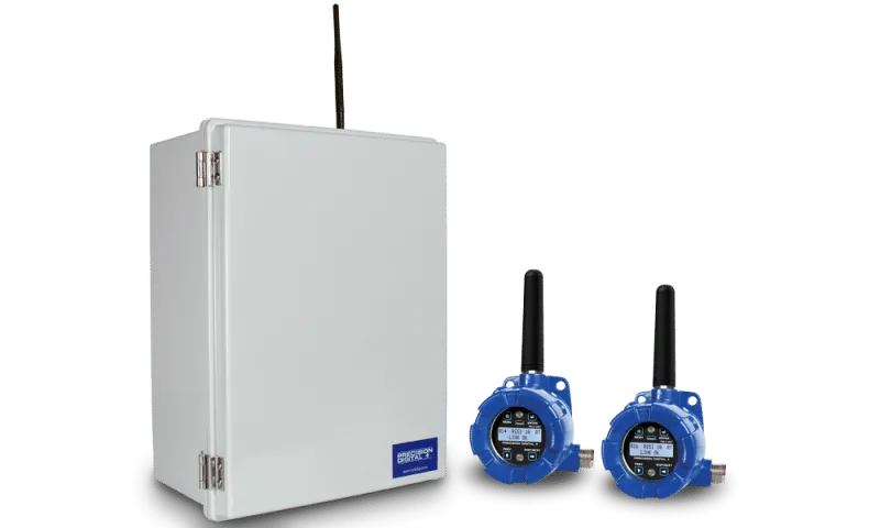
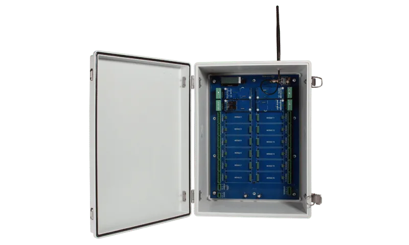
The Precision Digital PDW90 is a durable and customizable wireless bridge designed for point-to-multipoint communication. It provides a flexible solution for transmitting analog, digital, or Modbus® signals from one location to another. With modular input/output cards and expandable field units, the PDW90 can be tailored to fit any wireless application.

Ordering the PDW90 is straightforward, and configuring it is a breeze. You can choose from preassembled kits or individual modular components. Plus, it comes with a satisfaction guarantee—if it doesn’t meet your needs, you can return it hassle-free. For installations requiring longer distances, a wireless survey tool is available to ensure your setup will work effectively from the start.

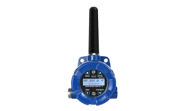
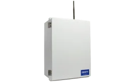
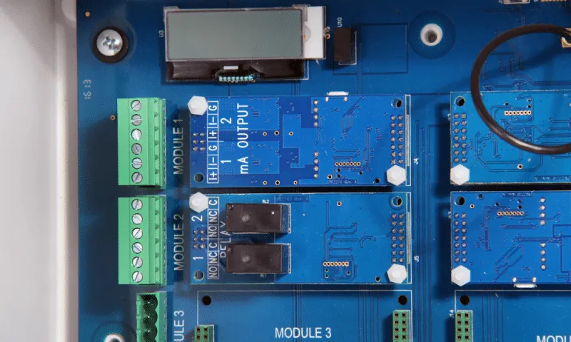
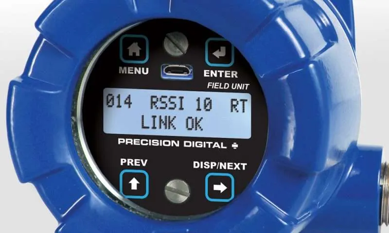
The field units can accept various inputs, including analog, discrete, or Modbus®, and they wirelessly transmit these signals to the PDW90 base station. The base station can then recreate these signals using its built-in RS-485 or analog and digital I/O cards. It can also be programmed to activate relays or send analog/digital signals back to the field units. Simply place the field units near your process signals and the base station in your control room.

Additionally, the PDW90 offers fixed or remote antenna modules along with a variety of accessories, such as mounting kits, antenna-related tools, and repeaters. You can attach the antenna directly or place it remotely, and high-gain directional antennas are also available for enhanced performance.

Features

  • Point to Multi-Point Signal Wire Replacement
  • Simple to Configure Using PDW Manager Programming
  • Software and Onboard USB
  • Range: 1 Mile Line-of-Sight, 500 Ft Indoor

Base Station

  • Rugged Plastic NEMA 4X Field Enclosure
  • Field or Wall Mounted
  • RS-485 Modbus Standard
  • Up to 16 Dual Input/Output Expansion Cards
  • Analog Input, Analog Output, Relay Output, and Digital I/O Cards Available

Field Units

  • Analog Input and Output, Four Digital I/O, and RS-485 Modbus® Standard
  • Remote or Attached Antenna
  • Flanges for Wall or Pipe Mounting
  • NEMA 4X, IP68 Enclosure

General

Maximum Connected Field Units

32 field units

Network ID

Programmable: 0 – 99

Programming Methods

Via PC with PDW Manager software

Power

24 VDC ±10%, 36 W max, 2.4 W min; Power consumption is dependent on type and number of modules installed

Non-Volatile Memory

All programmed settings are stored in non-volatile memory for a minimum of ten years if power is lost.

Environmental

Operating temperature range: -40 to 65°C; Storage temperature range: -40 to 85°C; Relative humidity: 0 to 90% non-condensing

Connections

Removable screw terminal blocks accept 12 to 22 AWG wire.

Peak Antenna Gain

2.15 dBi ± 1.0

Enclosure

15.75″ x 11.81″ x 7.03″ (40 cm x 30 cm x 17.9 cm) (W x H x D);
NEMA 4X; Thermoplastic Polyester; Color: Gray

Tightening Torque

Screw terminal connectors: 5 lb-in (0.56 Nm)

Shipping Dimensions

17″ x 14″ x 9″ (43.2 cm x 35.6 cm x 22.9 cm) (W x H X D)

Shipping Weight

6.5 lbs (2.95 kg)

Warranty

3 years parts & labor

Wireless Radio

Frequency

900 MHz

Range

500 ft (152.4 m) indoor, 1 mi (1.61 km) outdoor (line-of-sight)

Encryption

AES 128-bit encryption available using PDW Manager software

Interference Reduction

Frequency Hopping Spread Spectrum (FHSS)

Power Output

24 dBm (250 mW)

Sensitivity

-101 dBm

PDW Manager Software

System Requirements

Microsoft® Windows® XP/Vista/7/8/10

Communications

USB 2.0 (Standard USB A to Micro USB B)

Configuration

Configure devices one at a time

RS-485 Modbus® RTU Serial Communications

Compatibility

EIA-485

Connectors

Removable screw terminal connector

Max Distance

3,937′ (1,200 m) max

Baud Rate

1200 – 57,600 bps

Transmit Time Delay

Programmable between 0 and 199 ms

Data

8 bit (1 start bit, 1 or 2 stop bits)

Parity

Even, Odd, or None with 2 stop bits

Modbus Timeout

0.5, 1, 2, 3, 4, 5 seconds; user selectable

Inputs

Field selectable: 4-20 mA, 0-10 V, 0-5 V, 1-5 V

Accuracy

±0.03% of calibrated span ±1 count

Isolation

500 V

Recalibration

All ranges are calibrated at the factory. Recalibration is recommended at least every 12 months.

Temperature Drift

0.005% of calibrated span/°C max from 0 to 65°C ambient,
0.01% of calibrated span/°C max from -40 to 0°C ambient

Input Impedance

Voltage ranges: greater than 110 kΩ; Current ranges: < 220 Ω

Signal Loss

Inputs will remain off (open circuit) until wireless units are reconnected.

HART Transparency

Analog input will not interfere with existing HART communications on the wired 4-20 mA signal

Dual 4-20 mA Output Module

Output Source

Analog input from connected wireless unit

Calibration

Factory calibrated: 4.000 to 20.000 = 4-20 mA output

Accuracy

± 0.1% of span ± 0.004 mA

Isolation

500 V

Temperature Drift

0.4 µA/°C max from 0 to 65°C ambient,
0.8 µA/°C max from -40 to 0°C ambient

Loop Power Supply

Internally powered; no external supply needed

Output Loop Resistance

Power supply

Minimum

Maximum

24 VDC

10 Ω

900 Ω

Signal Loss

After approximately 25 seconds of trying to reconnect, mA output will become 3.2 mA

Digital Input / Output Module

Channels

Four (4) digital connections, independently field selectable as either inputs or outputs

Digital Input Logic High

3 to 5 VDC

Digital Input Logic Low

0 to 1.1 VDC

Digital Output Logic High

3 to 5 VDC

Digital Output Logic Low

0 to 0.4 VDC

Source Current

10 mA maximum output current

Sink Current

1.5 mA minimum input current

Signal Loss

Digital output goes to logic high

Dual Relays Module

Rating

2 SPDT (Form C); rated 3 A @ 30 VDC and 125/250 VAC resistive load; 1/14 HP (≈ 50 W) @ 125/250 VAC for inductive loads

Noise
Suppression

Noise suppression is recommended for each relay contact switching inductive loads; see page 13 for details.

Initialization

After power failure, relays will initialize to default state before reconnecting to wireless units.

Signal Loss

If mapped to digital input channel, the relay energizes.

PDW90 Field Unit Specifications

General

Display

32-character dual-line alphanumeric dot matrix LCD display with backlight
(4.68mm x 2.21mm characters)

Display Orientation

Display may be mounted at 180° from default orientation

Network ID

Field selectable: 0 – 99

Programming Methods

Four programming buttons (behind glass) or PC with PDW Manager software.

Recalibration

All inputs and outputs are calibrated at the factory. Recalibration is recommended at least every 12 months.

Process/ Digital I/O
Display

Press the display button once to display the present analog input and output, press the display button again to display digital I/O states.

Password

A programmable password restricts modification of programmed settings.

Power

12-28 VDC, 5 W max

Non-Volatile Memory

All programmed settings are stored in non-volatile memory for a minimum of ten years if power is lost.

Isolation

500 V

Environmental

Operating temperature range: -40 to 65°C (display inoperable < -20 °C); Storage temperature range: -40 to 85°C; Relative humidity: 0 to 90% non-condensing

Connections

Removable screw terminal blocks accept 16 to 30 AWG wire.

Enclosure

Cast aluminum with glass window, 0.30% max copper content, corrosion resistant powder coating, color: blue. NEMA 4X/IP68. Two ½” NPT threaded conduit openings. One ½” NPT stainless steel conduit plug with 10 mm hex key fitting installed.

Mounting

May be mounted directly to conduit. Two mounting holes for 1.5″ pipe or wall mounting. See Mounting Dimensions on page 15 for mounting space requirements.

Tightening Torque

2.5 lb-in (0.28 Nm)

Shipping Dimensions

17″ x 14″ x 9″ (43.2 cm x 35.6 cm x 22.9 cm) (L x W X H)

Shipping Weight

5 lbs. (2.27 kg)

Warranty

3 years parts & labor

Wireless Radio

Frequency

900 MHz

Range

500 ft (152.4 m) indoor, 1 mi (1.61 km) outdoor (line-of-sight)

Encryption

AES 128-bit encryption available using PDW Manager software

Interference Reduction

Frequency Hopping Spread Spectrum (FHSS)

Power Output

24 dBm (250 mW)

Sensitivity

-101 dBm

PDW Manager Software

System Requirements

Microsoft® Windows® XP/Vista/7/8/10

Communications

USB 2.0 (Standard USB A to Micro USB B)

Configuration

Configure devices one at a time

Analog Input

Inputs

Field selectable: 4-20 mA, 0-10 V, 0-5 V, 1-5 V

Accuracy

±0.03% of calibrated span ±1 count

Temperature Drift

0.005% of calibrated span/°C max from 0 to 65°C ambient,
0.01% of calibrated span/°C max from -40 to 0°C ambient

Input Impedance

Voltage ranges: greater than 110 kΩ; Current ranges: < 220 Ω

Signal Loss

Inputs will remain off (open circuit) until wireless units are reconnected.

HART Transparency

Analog input will not interfere with existing HART communications on the wired 4-20 mA signal

Isolated 4-20 mA Transmitter Output

Output Source

Analog input from connected wireless unit

Calibration

Factory calibrated: 4.000 to 20.000 = 4-20 mA output

Accuracy

± 0.1% of span ± 0.004 mA

Loop Power Supply

Internally powered; no external supply needed

Temperature Drift

0.4 µA/°C max from 0 to 65°C ambient, 0.8 µA/°C max from -40 to 0°C ambient

Signal Loss

mA output will become 3.2 mA after approx. 25 seconds

Output Loop Resistance

Power supply

Minimum

Maximum

24 VDC

10 Ω

900 Ω

Digital Input / Output Terminal

Channels

Four (4) digital connections, independently field selectable as either inputs or outputs

Digital Input Logic High

3 to 5 VDC

Digital Input Logic Low

0 to 1.1 VDC

DI Contact

Dry contact to ground can be used to activate the input

Digital Output Logic High

3 to 5 VDC

Digital Output Logic Low

0 to 0.4 VDC

Source Current

10 mA maximum output current

Sink Current

1.5 mA minimum input current

Signal Loss

Digital output goes to logic high

RS-485 Modbus® RTU Serial Communications

Compatibility

EIA-485

Connectors

Removable screw terminal connector

Max Distance

3,937′ (1,200 m) max

Baud Rate

1200 – 57,600 bps

Transmit Time Delay

Programmable between 0 and 199 ms

Data

8 bit (1 start bit, 1 or 2 stop bits)

Parity

Even, Odd, or None with 2 stop bits

Modbus Timeout

0.5, 1, 2, 3, 4, 5 seconds; user selectable

PDW90 Dimensions

Base Station

Field Unit

Base Station Connections

The diagrams below illustrate the layout of I/O module slots, screw terminal headers, wireless antenna connection, USB programming port, Modbus/power terminals, and LCD display for each base station size.

Base Station Wiring

Power

Connect power to the two-terminal block labeled POWER. Supply voltage: 9–30 VDC.

Power Connection Diagram

Dual Analog Input

Accepts 4-20 mA, 0-10 V, 0-5 V, or 1-5 V. Configure each channel independently. Compatible with HART loop signals (HART data not transmitted wirelessly).

Dual Analog Input Diagram

Dual Analog Output

Outputs 4-20 mA based on remote field unit input or Modbus register. Internally powered, no external supply required.

Dual Analog Output Diagram

Four Digital I/O

Each channel can be set as input or output. Inputs use internal pull-up resistors. Outputs can indicate loss of wireless signal.

Digital I/O Diagram

Dual Relay Outputs

Two mechanical relays, each with common (C), normally open (NO), and normally closed (NC) contacts. Active-low inputs may require swapping NO/NC connections.

Relay Output Diagram

Modbus RTU

Pass-through communication for multiple Modbus-enabled devices. Connect the Modbus Client to the Base Station.

Data Sheet: Predig_LDSW90-Datasheets
Instruction Manual: Predig_PDW90_Manual

Shopping Cart