Model: PD8-6060-7H5
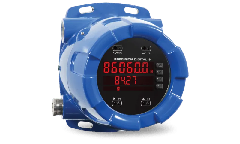
Product Type: Explosion-Proof Dual Process Input Meter
Input: Current (4-20 mA), Dual Inputs, Voltage (0-10 V)
Output Options: 2 Relays & 4-20 mA Output
Power: 12-24 VDC/VAC
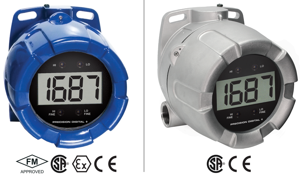
Approvals: ATEX (FP), CE, CSA (XP), FM (XP), IEC (FP)
Transmitter Power: 24 VDC @ 25 mA + 24 VDC @ 25 mA
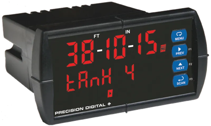
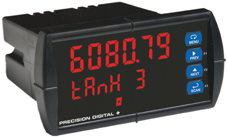
Display Category: LED, Dual Line, Sunlight Readable
Display: SunBright, 0.6″, Dual Line, 6 Digits, Red LED
Warranty: 3 years
Product Series: ProtEX MAX
Product Family: PD8-6060
Product Category: Explosion-Proof, Field Mounted Indicators
Product Application: Level, Pressure, Process, Hazardous Area, Pump Control
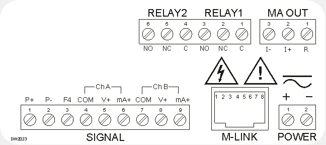
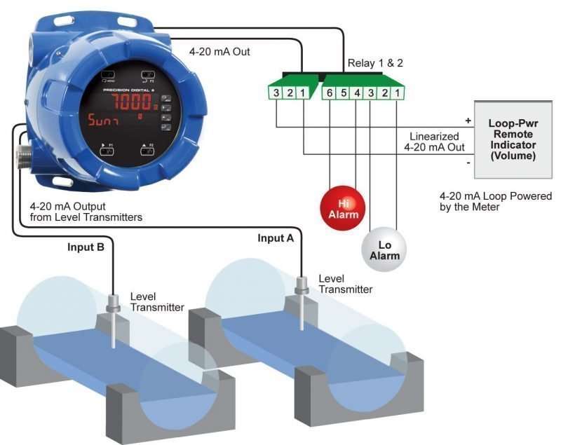
Wiring Diagram:
General
Display: Upper display: 0.60″ (15 mm) high. Lower display: 0.46″ (12 mm) high. Both are 6 digits (-99999 to 999999), red LEDs
Display Intensity: Eight user selectable intensity levels
Display Update Rate: 5/second (200 ms)
Overrange: Display flashes 999999
Underrange: Display flashes -99999
Display Assignment: The Upper and Lower displays may be assigned to process values for Channels A (Ch-A), B (Ch-B), or C (Ch-C), toggle between (Ch-A & Ch-B, Ch-A & Ch-C, Ch-B & Ch-C, and Ch-A, Ch-B,& Ch-C), toggle between Channel & units, show channel gross value (no tare) or toggle net (tare) and gross values, show relay set points, max& min values, or Modbus input. The second display may also be set to show engineering units or be off, with no display.
Programming Methods: Four through-glass SafeTouch buttons, four mechanical buttons behind glass, digital inputs, PC and MeterView Pro software, or Modbus registers.
F4 Digital Input Contacts: 3.3 VDC on contact. Connect normally open contacts across F4 to COM.
F4 Digital Input Logic Levels: Logic High: 3 to 5 VDC; Logic Low: 0 to 1.25 VDC
Noise filter: Programmable from 2 to 199 (0 will disable filter)
Filter Bypass: Programmable from 0.1 to 99.9% of calibrated span
Recalibration: All ranges are calibrated at the factory. Recalibration is recommended at least every 12 months.
Max/Min Display: Max (Peak) / min (Valley) readings reached by the process are stored until reset by the user or until power to the meter is cycled.
Password: Three programmable passwords restrict modification of programmed settings.
Non-Volatile Memory: All programmed settings are stored in nonvolatile memory for a minimum of ten years if power is lost.
Power Options: 85-265 VAC 50/60 Hz, 90-265 VDC, 20 W max, or optional sku with 12-24 VDC ±10%, 15 W max.
Fuse: Required external fuse: UL Recognized, 5 A max, slow blow; up to 6 meters may share one 5 A fuse.
Isolated Transmitter Power Supply: Terminals P+ & P-: 24 VDC ± 10%. Isolated from the input at >500 V. Jumper selectable for 24, 10, or 5 VDC supply (internal jumper J4). All skus transmitter supply rated @ 25mA max.
Normal Mode Rejection: Greater than 60 dB at 50/60 Hz
Isolation: 4 kV input/output-to-power line. 500 V input-to-output or output-to-P+ supply.
Overvoltage Category: Installation Overvoltage Category II: Local level with smaller transient overvoltages than Installation Overvoltage Category III.
Environmental:
T6 Class operating temperature range Ta = -40 to 60°C
T5 Class operating temperature range Ta = -40 to 65°C
See LIM8 ProtEX-MAX instruction manual for additional details.
Max Power Dissipation: PD8 Series: Maximum power dissipation limited to 15.1 W. See PD8 instruction manual for additional details.
Connections: Removable screw terminal blocks accept 12 to 22 AWG wire, RJ45 for external relays, digital I/O, and serial communication adapters.
Enclosure: Explosion-proof die cast aluminum with glass window, corrosion resistant epoxy coating, color: blue. NEMA 4X, 7, & 9, IP68. Default conduit connections: Four ¾” NPT threaded conduit openings and two ¾” NPT metal conduit plugs with 12 mm hex key fitting installed. Additional conduit opening configurations may be available; verify quantity and sizes on specific device labeling during installation.
Mounting: Four slotted flanges for wall mounting or NPS 1½” to 2½” or DN 40 to 65 mm pipe mounting
Dimensions: 6.42″ x 7.97″ x 8.47″ (W x H x D) (163 mm x 202 mm x 215 mm)
Weight: 16.0 lbs (7.26 kg)
Warranty: 3 years parts & labor
USB Connection: Compatibility: USB 2.0 Standard, Compliant
Connector Type: Micro-B receptacle
Cable: USB A Male to Micro-B Cable
Driver: Windows 98/SE, ME, 2000, Server 2003/2008, XP 32/64-Bit,
Vista 32/64-Bit, Windows 7 32/64-Bit, Windows 10 32/64-Bit
Power: USB Port
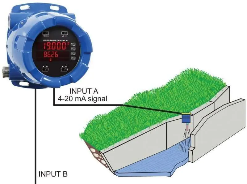
Dual Process Input
Inputs: Two inputs, each separately field selectable: 0-20, 4-20 mA, 10 V (0-5, 1-5, 0-10 V), Modbus PV (Slave)
Channels: Channel A, Channel B, Channel C (Math channel)
Programmable Constants: Constant P (Adder): -99999 to 999999, default: 0.000; Constant F (Factor): 0.00001 to 999999, default: 1.000
Math Functions: Addition, difference, absolute difference, average, multiplication, division, max of A or B, min of A or B, draw, weighted average, ratio, concentration. See instruction manual for details.
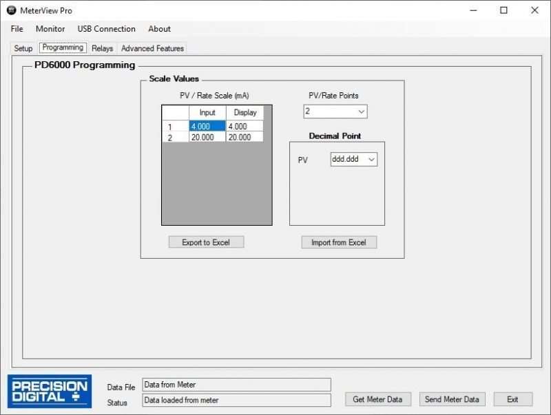
Sequence of Operations for Input Programing:
- Select Input for A and B
- Set up the engineering units for A, B, and C
- Set up decimal point for A, B, and C
- Scale A & B
- Set up the displays for A, B, or C
- Select the transfer function for A & B (e.g. Linear)
- Select Math function for Channel C
- Program constants for Factor (F) and Adder (P).
- Program cutoff values for A and B
Accuracy: ±0.03% of calibrated span ±1 count, square root & programmable exponent accuracy range: 10-100% of calibrated span
Temperature Drift: 0.005% of calibrated span/°C max from 0 to 65°C ambient, 0.01% of calibrated span/°C max from -40 to 0°C ambient
Signal Input Conditioning: Linear, square root, programmable exponent, or round horizontal tank volume calculation.
Multi-Point Linearization: 2 to 32 points for channel A and B
Programmable Exponent: 1.0001 to 2.9999
Low-Flow Cutoff: 0-999999 (0 disables cutoff function)
Decimal Point: Up to fi ve decimal places or none: d.ddddd, dd.dddd, ddd.ddd, dddd.dd, ddddd.d, or dddddd.
Calibration Range: 4-20 mA: minimum span input 1 & input 2: 0.15 mA. ±10 V: minimum span input 1 & 2: 0.10 V. An error message will appear if input 1 and input 2 signals are too close together.
Input Impedance: Voltage ranges: greater than 500Ω. Current ranges: 50 – 100Ω (depending on resettable fuse impedance).
Input Overload: Current input protected by resettable fuse, 30 VDC max. Fuse resets automatically after fault is removed.
HART Transparency: Analog input will not interfere with existing HART communications on the wired 4-20 mA signal
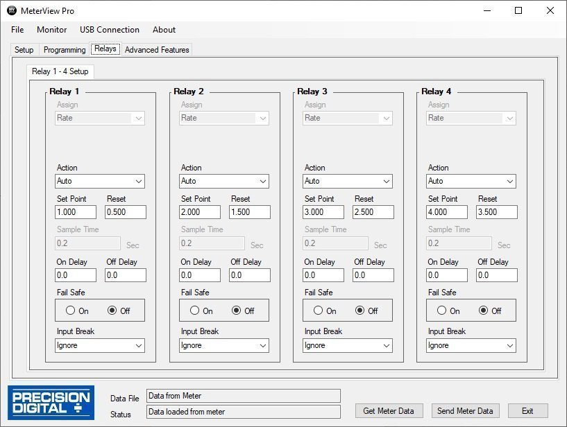
Relays
Rating: 2 or 4 SPDT (Form C) internal and/or 4 SPST (Form A) external; rated 3 A @ 30 VDC and 125/250 VAC resistive load; 1/14 HP
(≈50 W) @ 125/250 VAC for inductive loads.
Noise Suppression: Noise suppression is recommended for each relay contact switching inductive loads.
Deadband: 0-100% of span, user programmable
High or Low Alarm: User may program any alarm for high or low trip point. Unused alarm LEDs and relays may be disabled (turned off).
Relay Operation: Automatic (non-latching), latching (requires manual acknowledge), sampling (based on time), pump alternation control (2 to 8 relays), Off (disable unused relays and enable interlock feature, manual on/off control mode).
Relay Reset: User selectable via front panel buttons or digital inputs.
- Automatic reset only (non-latching), when input passes the reset point.
- Automatic + manual reset at any time (non-latching).
- Manual reset only, at any time (latching).
- Manual reset only after alarm condition has cleared (latching).
Note: Front panel button or digital input may be assigned to acknowledge relays programmed for manual reset.
Time Delay: 0 to 999.9 seconds, on & off relay time delays. Programmable and independent for each relay.
Fail-Safe Operation: Programmable and independent for each relay.
Note: Relay coil is energized in non-alarm condition. In case of power failure, relay will go to alarm state.
Auto Initialization: When power is applied to the meter, relays will reflect the state of the input to the meter.
Serial Communications
Compatability: EIA-485
Connectors: Removable screw terminal connector
Max Distance: 3,937′ (1,200 m) max
Status Indication: Separate LEDs for Power (P), Transmit (TX), and Receive (RX)
Protocol: Modbus® RTU
Meter Address/Slave ID: 1 – 247
Baud Rate: 300 – 19,200 bps
Transmit Time Delay: Programmable between 0 and 199 ms
Data: 8 bit (1 start bit, 1 or 2 stop bits)
Parity: Even, odd, or none with 1 or 2 stop bits
Byte-to-Byte Timeout: 0.01 – 2.54 seconds
Turn Around Delay: Less than 2 ms (fixed)
Isolated 4-20 mA Transmitter Output
Output Source: Process channel A, B, or C, max or min for channel A, B, or highest or lowest max or min of A and B, set points 1-8, Modbus input, or manual control mode
Scaling Range: 1.000 to 23.000 mA for any display range
Calibration: Factory calibrated: 4.000 to 20.000 = 4-20 mA output
Analog Output Programming: 23.000 mA maximum for all parameters: Overrange, underrange, max, min, and break
Accuracy: ±0.1% of span ±0.004 mA
Temperature Drift: 0.4 µA/°C max from 0 to 65°C ambient, 0.8 µ/°C max from -40 to 0°C ambient
Note: Analog output drift is separate from input drift.
Isolated Transmitter Power Supply: Terminals I+ & R: 24 VDC ± 10%. Isolated from the input at >500 V. May be used to power the 4-20 mA output or other devices. All skus @ 25 mA max.
External Loop Power Supply: 35 VDC maximum
Output Loop Resistance:
| Power supply | Minimum | Maximum |
| 24 VDC | 10 Ω | 700 Ω |
| 35 VDC (external) | 100 Ω | 1200 Ω |
Digital Inputs and Outputs
Channels: 4 digital inputs & 4 digital outputs per module
System: One expansion module may be added for a total of 8 inputs & 8 outputs
Note: The jumper located between the RJ45 connectors must be removed on the expansion module.
Digital Input Logic: High: 3 to 5 VDC; Low: 0 to 1.25 VDC
Digital Output Logic: High: 3.1 to 3.3 VDC; Low: 0 to 0.4 VD
Source Current: 10 mA maximum output current
Sink Current: 1.5 mA minimum input current
+5 V Terminal: To be used as pull-up for digital inputs only. Connect normally open pushbuttons across +5 V & DI 1-4. Warning: DO NOT use +5 V terminal (pin 1) to power external devices.
Function Assignment: The on-board digital inputs (1-4) are designed to mimic the behavior of the front panel buttons (Menu, F1, F2, & F3). If you wish to change their behavior, re-assign F1-F3 to the desired function, then change the corresponding digital input to match.
4-Relay Expansion Module
Relays: Four Form A (SPST) rated 3 A @ 30 VDC and 125/250 VAC resistive load; 1/14 HP (approx. 50 watts) @ 125/250 VAC for inductive loads.
Dual Analog Output Expansion Module
Outputs: Two passive 4-20 mA analog outputs
Scaling Range: 3.000 to 23.000 mA for any display range
Product Ratings and Approvals
FM Enclosure: Type 4X; IP66
Class I, Division 1, Groups B, C, D
Class II, Division 1, Groups E, F, G
Class III, Division 1, T5/T6
Class I, Zone 1, AEx d, IIC Gb T5/T6
Zone 21, AEx tb IIIC T90°C; Ta -40°C to +65°C
T6 Ta = -40°C to +60°C; T5 Ta = -40°C to +65°C
Certificate Number: 3047283
CSA: Class I, Division 1, Groups B, C, D
Class II, Division 1, Groups E, F, G
Class III, Division 1
Class I Zone 1 Ex d IIC
Zone 21 Ex tb IIIC T90°C
-40°C < Tamb. < +60° C; Temperature Code T6
-40°C < Tamb. < +65° C; Temperature Code T5
Enclosure Type 4X & IP66
Certificate Number: 2531731
ATEX: II 2 G D Ex d IIC T* Gb
Ex tb IIIC T90°C Db IP68
Ta = -40°C to +*°C
*T6 = -40°C to +60°C
*T5 = -40°C to +65°C
Certificate number: Sira 12ATEX1182
IECEx: Ex d IIC T* Gb
Ex tb IIIC T90°C Db IP68
Ta = -40°C to +*°C
*T6 = -40°C to +60°C
*T5 = -40°C to +65°C
Certificate Number: IECEx SIR 12.0073

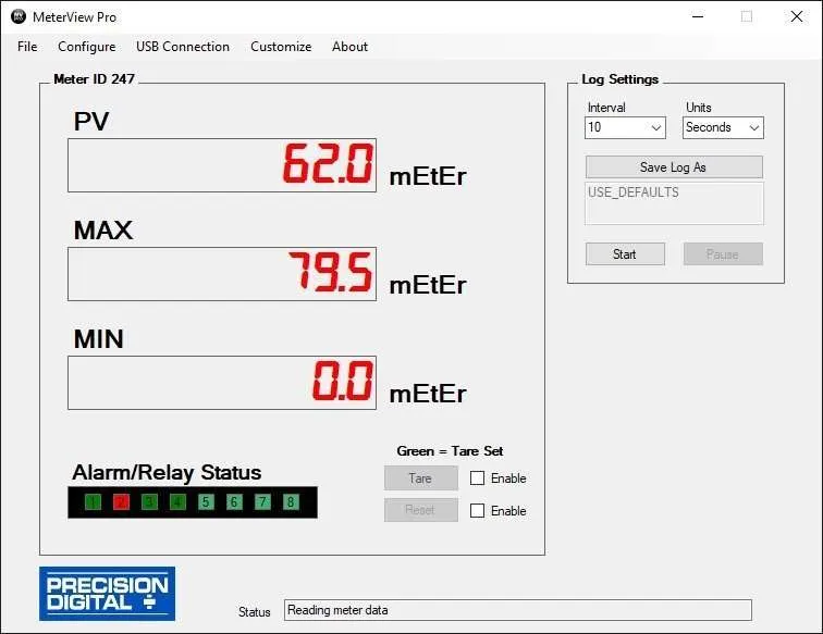
 MeterView® Pro software is designed for use with
  ) and press Enter button.
 ).
). ), version (
 ), and serial number (
 ) information. Write down the information as it is displayed. Continue pressing Enter until all the information is displayed.